Dremel DigiLab 3D45 - Controller Rebuild
Rebuilding a Dremel DigiLab 3D45 after the original motherboard was damaged during fan voltage testing.
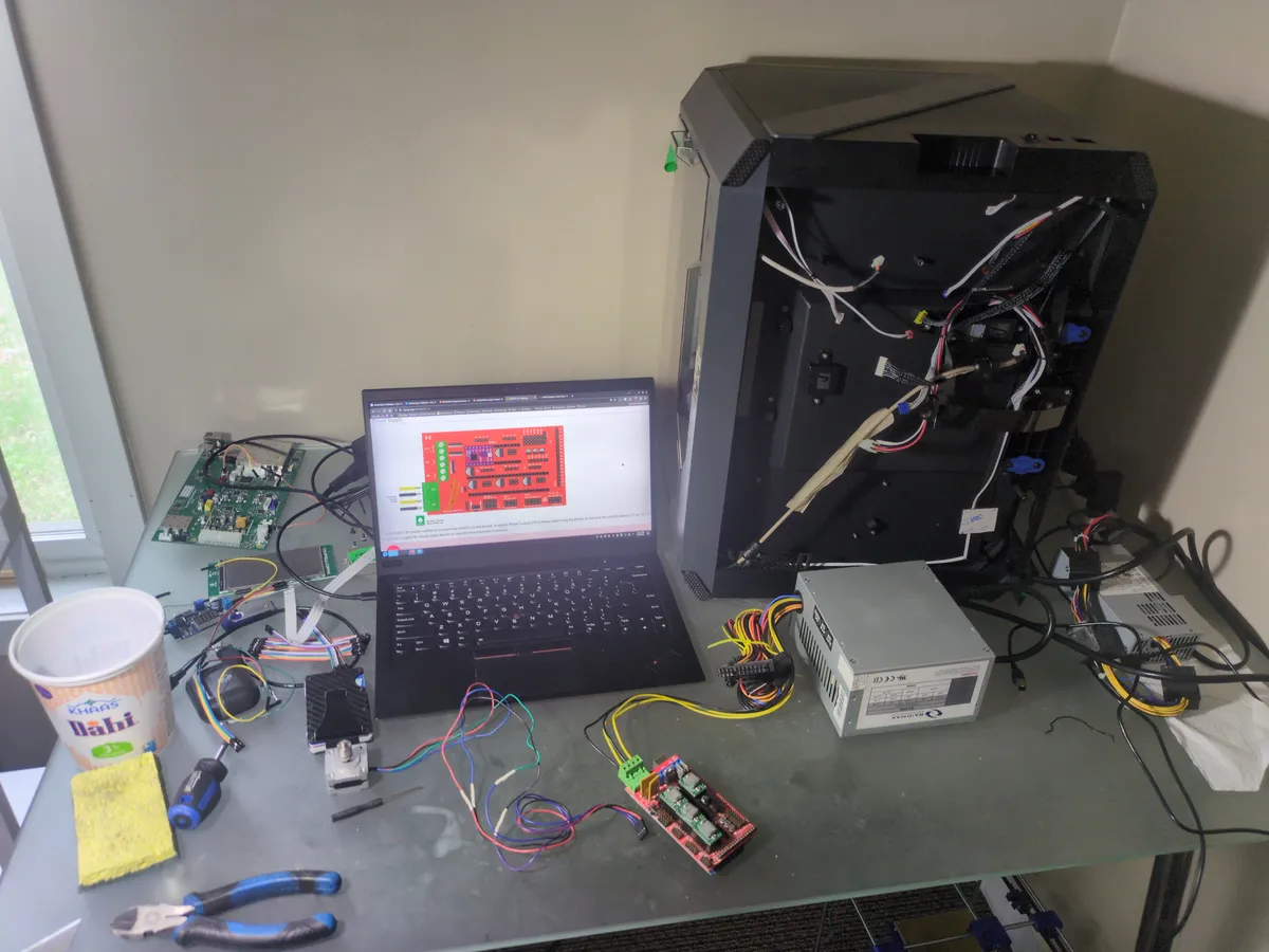
This project started after I accidentally fried the printer's motherboard while testing an output voltage for the turbo fan. The failure took out the drivers and left the printer completely dead. Instead of treating the machine as a loss, I rebuilt it around an Arduino Mega 2560 and RAMPS 1.4 board pulled from another broken printer I had salvaged from an electronics waste bin.
In Progress
This rebuild is still ongoing. More photos, wiring details, and firmware notes will be added as the project continues.
Project Focus
The goal was to keep the Dremel's higher-value frame and chassis while replacing the failed control electronics with something I could maintain and iterate on more easily. I stripped usable parts from the donor printer and used them to rebuild the Dremel's control system instead of trying to source proprietary replacement boards.
Build Summary
Core Hardware
- Arduino Mega 2560
- RAMPS 1.4 board
- A4988 stepper drivers
- TMC2209 stepper drivers
Current State
- Phase: Rebuild and validation
- Status: In progress
- Scope: Electronics replacement and printer recovery
Initial Failure
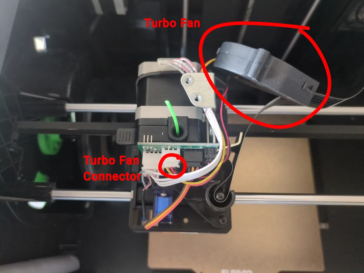
After the first rebuild, the printer was actually printing parts again. But once I let it run for a while, I started running into heat creep. My first thought was that the turbo fan might not be getting the right voltage. Since the printer is proprietary, it never really tells you what the fan is supposed to run at, so I grabbed a multimeter and checked the connector myself. While I was probing the fan lines, I accidentally touched the red positive lead to the yellow tachometer signal line. Right after that, the printer started acting dead on the higher-voltage side. The motors stopped, and the heating element was only getting about 5 volts, which was nowhere near enough to heat the block. The screen and lights still worked, so I knew the 5V side was fine, but everything else had clearly been knocked out. That was what pushed me to test the motherboard and PSU, hoping I only tripped a fuse.
Step 1: Diagnosing the Problem
The first stage of the rebuild was diagnosis. I started by isolating the power system and checking the printer's incoming power path before moving any deeper into the electronics.
Step 1.1: PSU Inspection and Output Testing
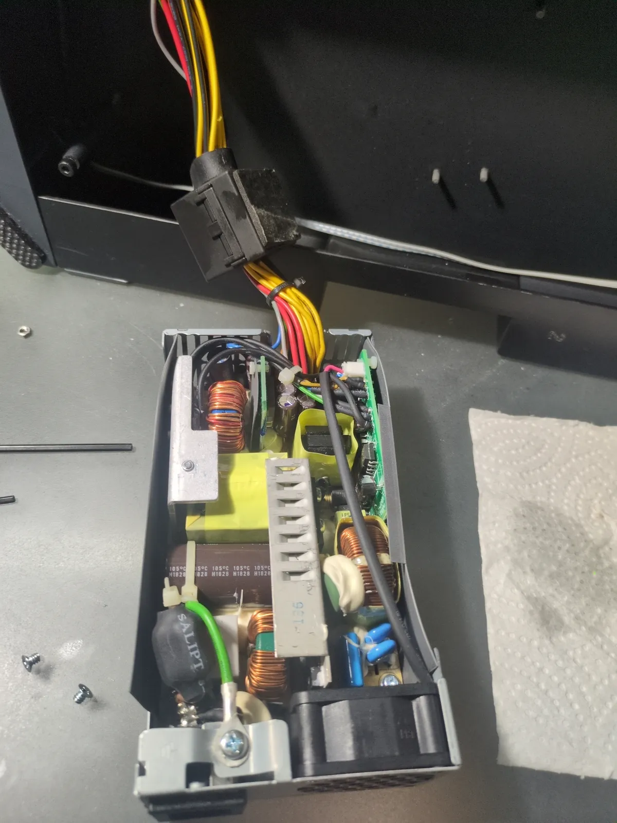
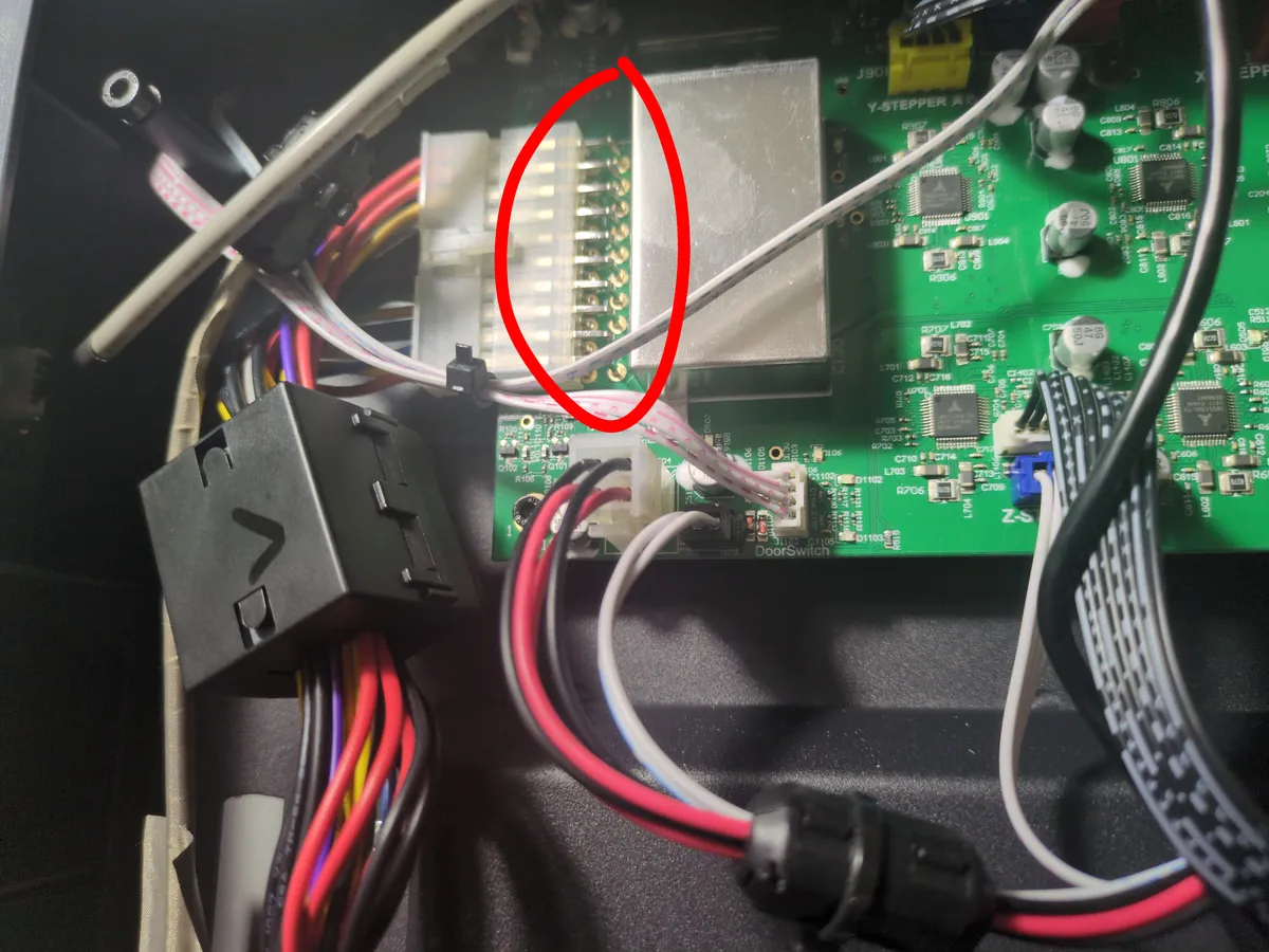
I removed the PSU and opened it up to inspect it for any obvious shorting, damage, or burnt components, but I did not push much further at that point because I knew enough to respect the risks of working inside a power supply without more experience. After putting it back in and confirming it powered up normally, I moved on to testing the output wiring. The goal there was to verify the voltage coming off the PSU leads while the wiring was still connected to the motherboard, so I could compare the supply output against what was actually reaching the board and look for any discrepancies in the path.
Step 1.2: Motherboard Driver Testing
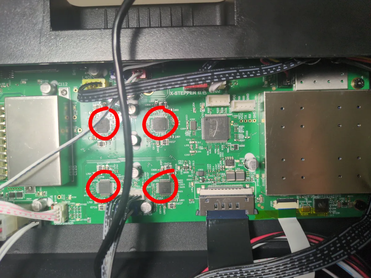
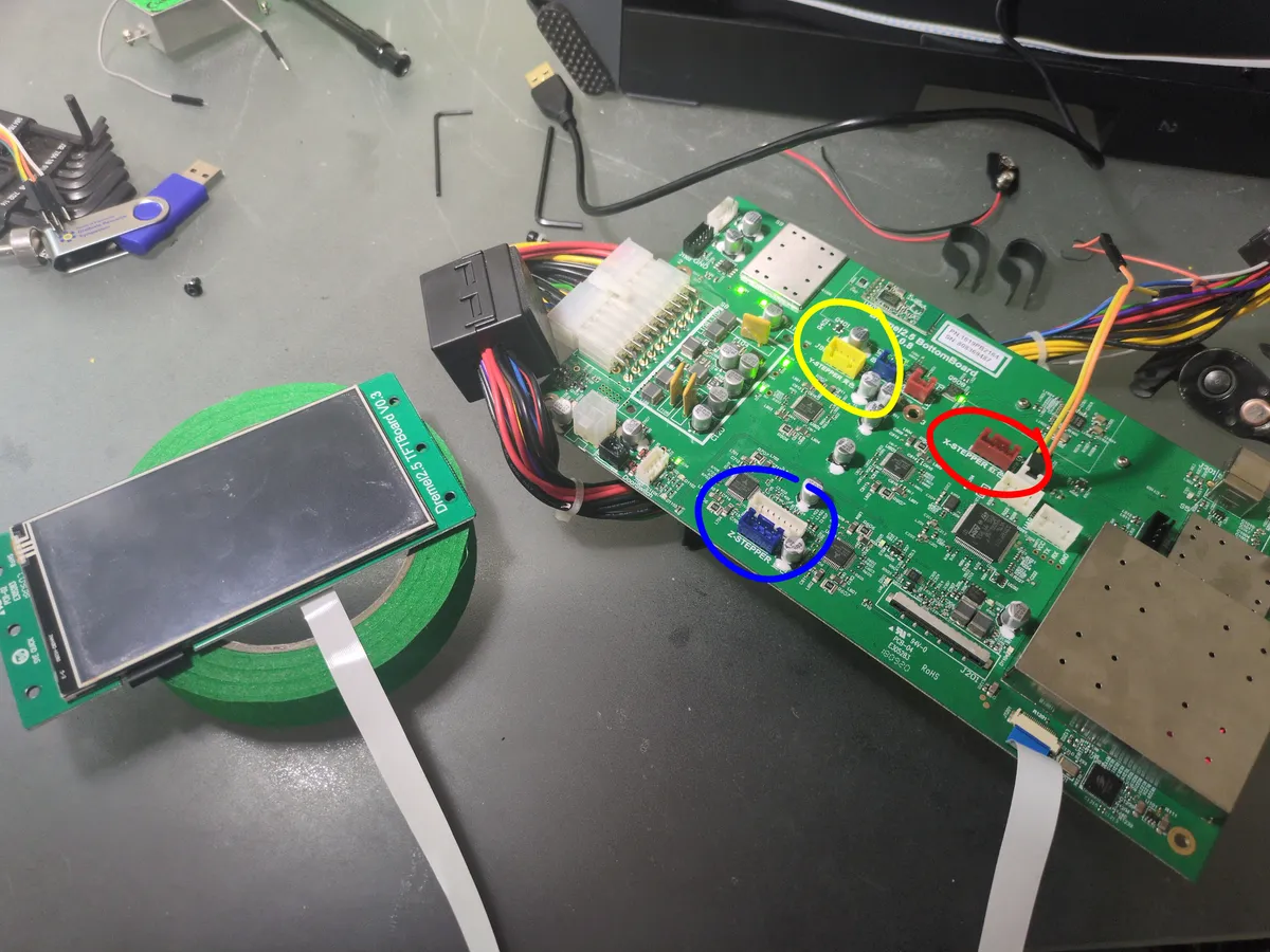
From there I moved deeper into the control board itself. I started by tracing the major driver stages on the motherboard and identifying which controller chips were responsible for the printer's motion and toolhead functions. At this point I was not trying to repair the board yet. I was trying to understand how the board was laid out so I could decide which sections were worth testing and which signals I needed to measure next.
Once I understood the board layout, I moved on to output testing. I checked the stepper motor outputs one axis at a time and compared the readings against what the printer was being told to do in jog mode. The goal was to see whether the board was actually changing state when the motors were commanded to move, or whether the output stage was stuck in a bad state. The readings stayed at roughly 12V across the outputs no matter what command I sent, and they also sat at 12V while idle. That was a strong sign that the driver stage was not behaving normally and was likely shorted or otherwise damaged.
Step 2: Verifying the Donor Hardware
Once I had narrowed the failure down to the Dremel's control electronics, the next step was to replace the damaged motherboard with the Arduino Mega 2560 and RAMPS 1.4 setup I had salvaged from the donor hobby printer. Before I trusted that hardware inside the Dremel, I first treated it like its own repair project and verified that the donor printer's board, power, and motors were actually healthy enough to reuse.
Step 2.1: Donor Board and Motor Verification
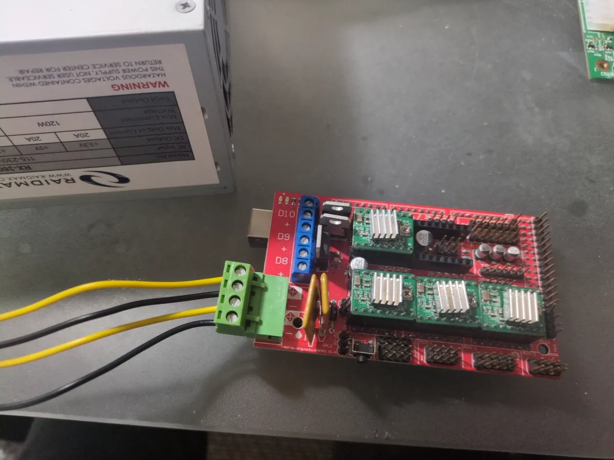
Before I committed the donor hardware to the Dremel rebuild, I verified it as a separate system. I powered the Arduino Mega and RAMPS board with the donor printer's PSU first so I could make sure the replacement electronics would come up cleanly on their own. That was important because the donor printer came from an electronics bin and had already been partially disassembled, so I could not assume any of its wiring, power delivery, or motion hardware was still reliable.
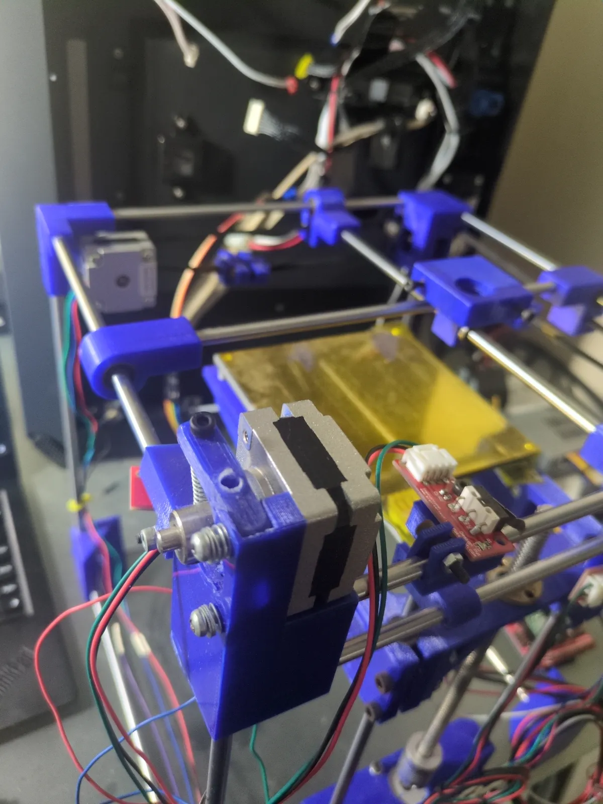
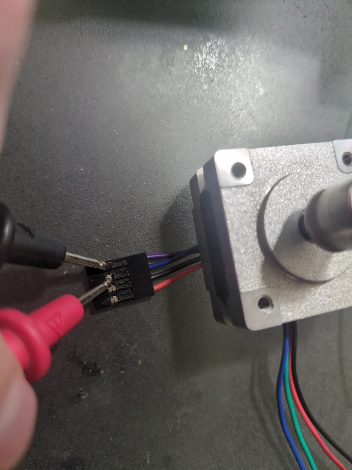
I then tested a stepper motor directly so I could map its four wires into the two coil pairs the driver needs. That step matters because a stepper motor is not wired like a normal DC motor. It depends on the controller energizing the correct coils in the correct order, so I had to identify the paired wires before I could safely connect it to RAMPS.
Step 2.2: Flashing Marlin and Testing Motion
Once the donor board and motor wiring checked out, I flashed the Marlin firmware to the Arduino Mega and wrote a simple python script to connect my left and right arrow keys to a few simple G-code commands to verify all the systems would work before moving to rebuilding the Dremel printer with the donor electronics.
Step 3: Setting the Driver Current and Wiring the Motors
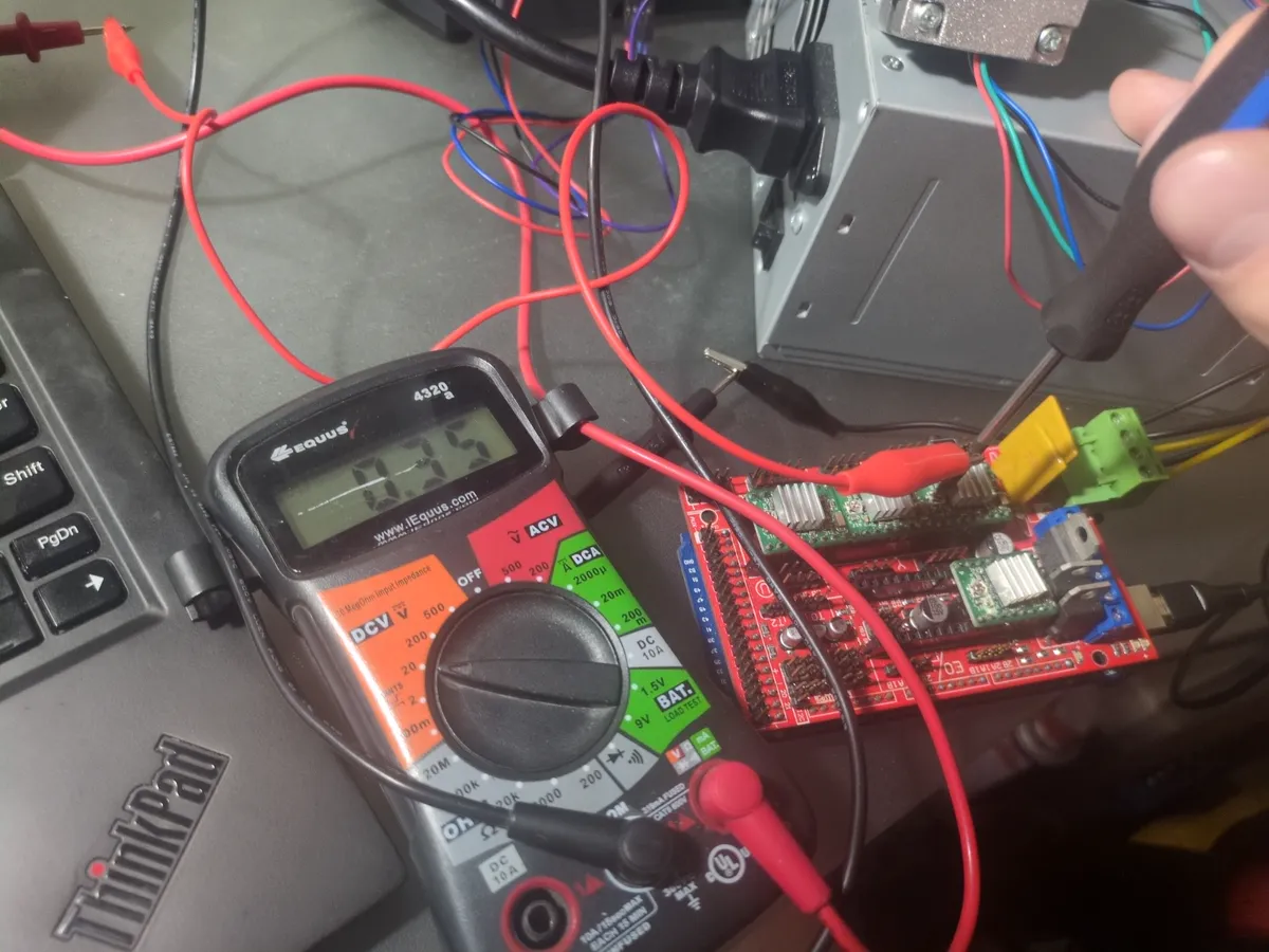
With the firmware and basic motion test working, I moved on to matching the driver current to the motors the Dremel actually uses. I looked up the motor specifications, used that information to calculate an approximate VREF target for the A4988 drivers, and then adjusted the trimpots until the drivers were set close to the current the printer needed. That step matters because the drivers need enough current to move the motors reliably, but not so much that they run hot or stress the hardware unnecessarily.
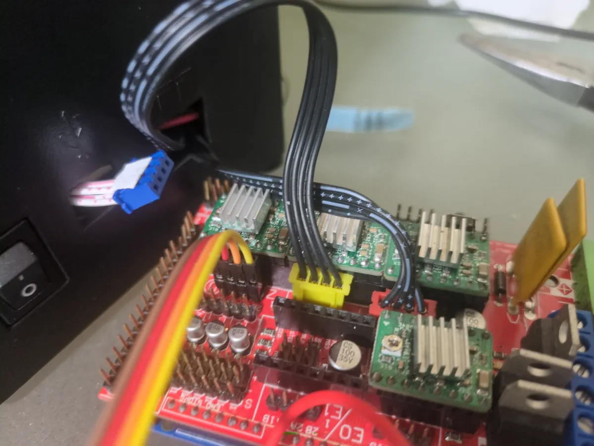
After that, I wired the X, Y, and Z motors to the correct RAMPS output pins. The point of the wiring was to make sure each axis was assigned to the driver channel that Marlin expected, so the motors would respond to the proper movement commands instead of being mixed up or reversed. Once that was in place, the replacement control system was no longer just powered on and tested in pieces. It was starting to behave like the actual motion controller for the rebuilt printer.
Step 4: Writing Jog Mode Control
Once the motion system was stable, I wrote a Python script to make jog mode easier to use during testing. The goal was to control the X, Y, and Z axes directly from the keyboard so I could move the printer in small, deliberate increments without constantly typing manual commands.
I mapped the arrow keys to X and Y movement and used Page Up and Page Down for Z movement. That gave me a simple control layer for the printer while I was checking alignment, verifying motion response, and making sure the rebuilt electronics behaved the way they should under manual control.
Rebuild Approach
I treated the donor printer as a parts source and rebuilt the Dremel around the Arduino Mega 2560 and RAMPS 1.4 setup. At first I reused the original A4988 drivers, then later moved to TMC2209 drivers. I also replaced the damaged control hardware more than once after another failure, which meant buying fresh Mega, RAMPS, and TMC2209 parts and wiring everything back up again.
Why This Printer
The Dremel itself is the better machine to keep because of its frame and chassis quality, which gives it better consistency and precision than the donor printer. The plan was to preserve the stronger mechanical foundation and swap in the usable electronics and motors from the broken machine rather than starting over.
Closing Thoughts
This is still a work in progress, but the rebuild already reflects the direction I want to take it: recover the better machine, reuse salvageable hardware where it makes sense, and keep iterating until the printer is reliable again.