Dremel DigiLab 3D45 - Restoration
Documentation of the teardown, diagnosis, and repair of a Dremel DigiLab 3D45 printer.
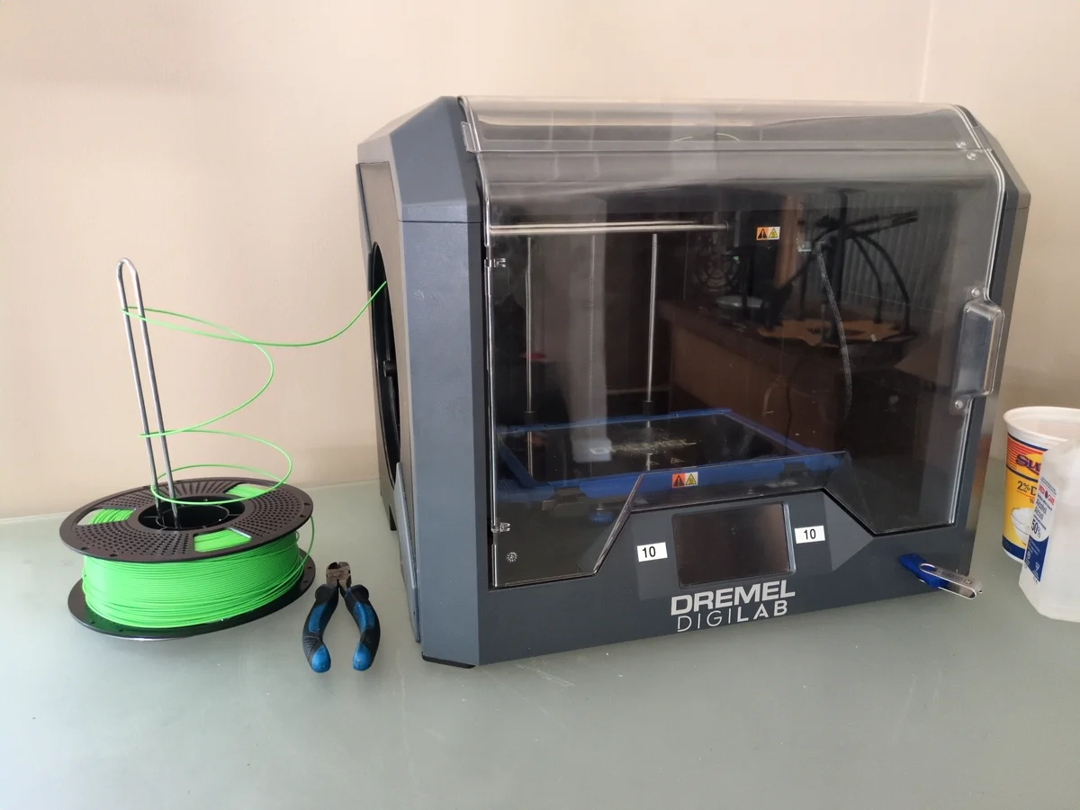
I was gifted a Dremel 3D45 printer that had been sitting unused for a year or so. It was in non-functional condition and in complete disarray, with multiple parts scattered everywhere. Much of it was still intact, specifically the frame, motion system, and power supply. The hotend however, was completely dismantled and missing several components. I had also aquired a second hobby printer from an electronics waste bin, which I attempted to salvage parts from to fix the Dremel 3D45 printer. However, the incompatibility made this unrealistic and the easier approach was to replace or fix the broken and missing parts. (Dremel 3D printers are also heavily proprietary so this made things a little trickier).
Initial Diagnosis
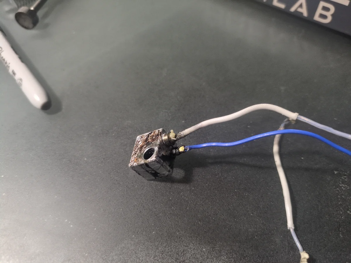
The frame, motion system, and power supply were all intact. The hotend was dismantled with broken wires, old PLA filament fused to the many components, and the nozzle was missing. The extruder drive gear was still intact and potentially functional, just disconnected. It seemed that all I would need to do is buy a new hotend assembly for a bit over $100 CAD and I would be good to go. However I gave myself the challenge to repair it as cheaply as possible.
Repair Overview
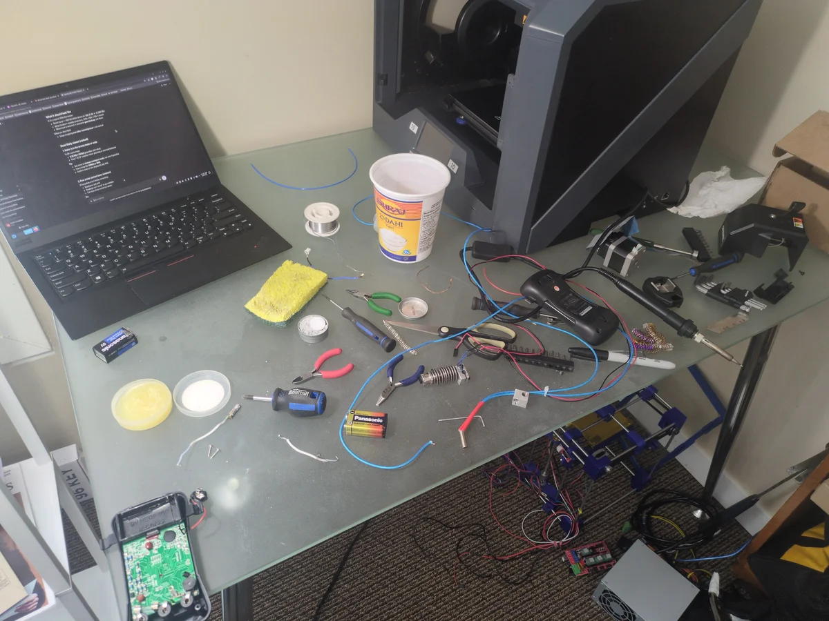
Parts and Tools
- Nozzle 0.4mm ($35)
- Tap 8mm-1.25 ($10)
- Screws ($1)
Quick Stats
- Total Cost: $46
- Time Spent: 3 Days
- Difficulty: 3/5 (Technical Repair)
*For the 3D45.ini configuration file, please view the Dremel DigiLab 3D45 - Modification project.*
Step 1: Specs & Analysis
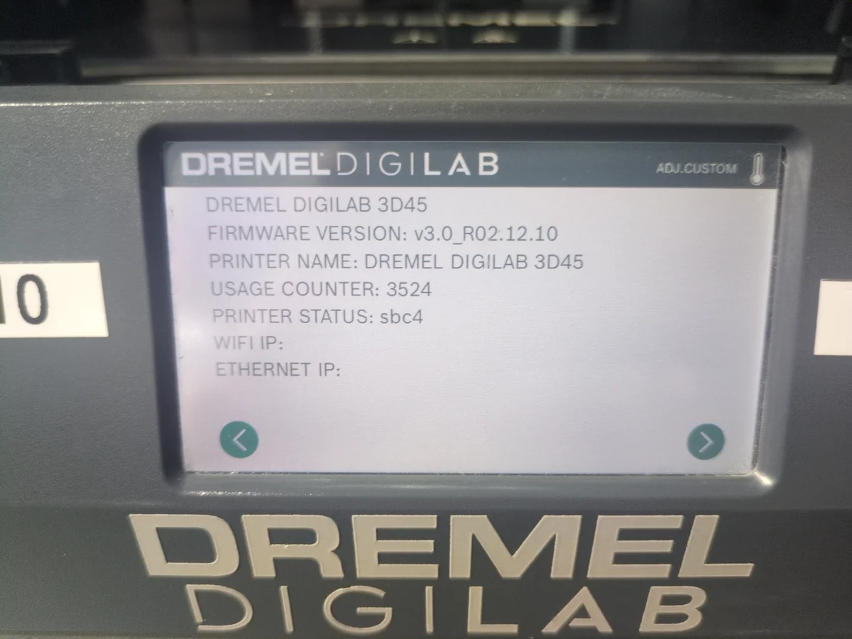
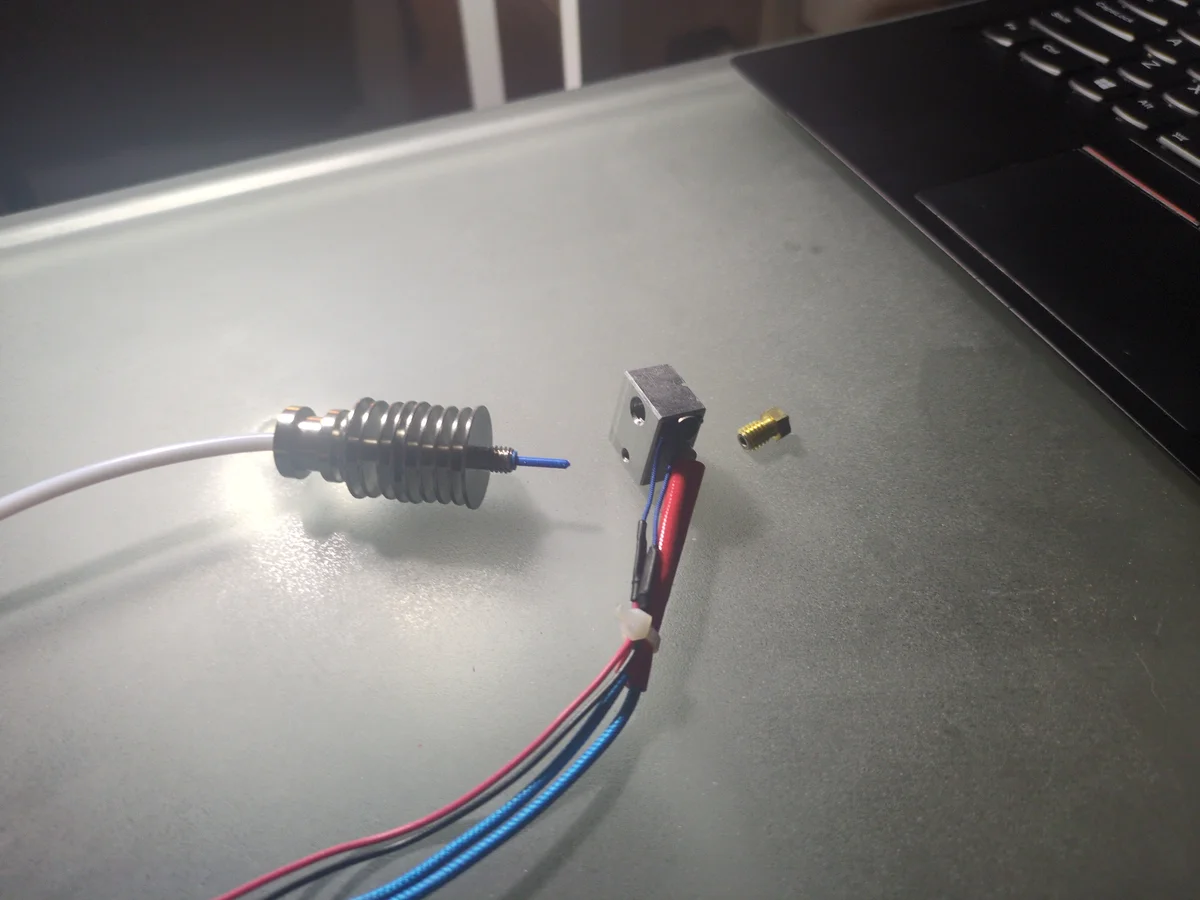
Turning the printer on revealed that the main board was still functional, as the screen lit up and the fans spun. I looked through the settings to find the specs of the printer which I thought might come in handy later. I then proceeded to analyze the broken parts of the hotend that came with the printer.
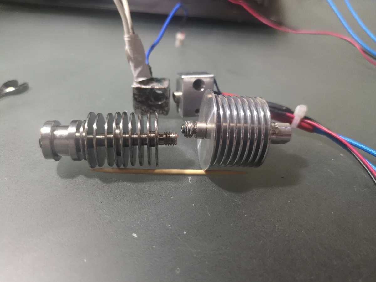
Step 2: Attempt Hotend Transplant
Dismantling the hotend from the second printer, I attempted to use it to replace the broken one on the Dremel 3D45. However, I quickly realized that the two printers were not compatible with each other. The hotend was too tall to fit in the Dremel's print head assembly, and the threading of the individual components was completely different. My plan was then to add some sort of "sleeve" for the nozzle of the second printer to fit in the hot end of the Dremel printer since it was much smaller and the threading wouldn't match. Because of the precise tolerances of 3D printers, this was not a realistic option and I ended up just ordering a 3rd party replacement nozzle online.
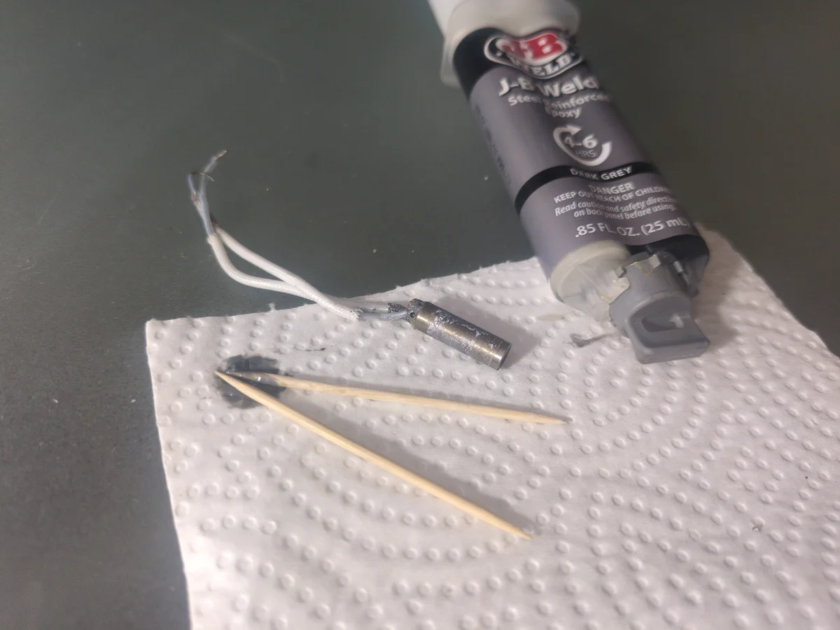
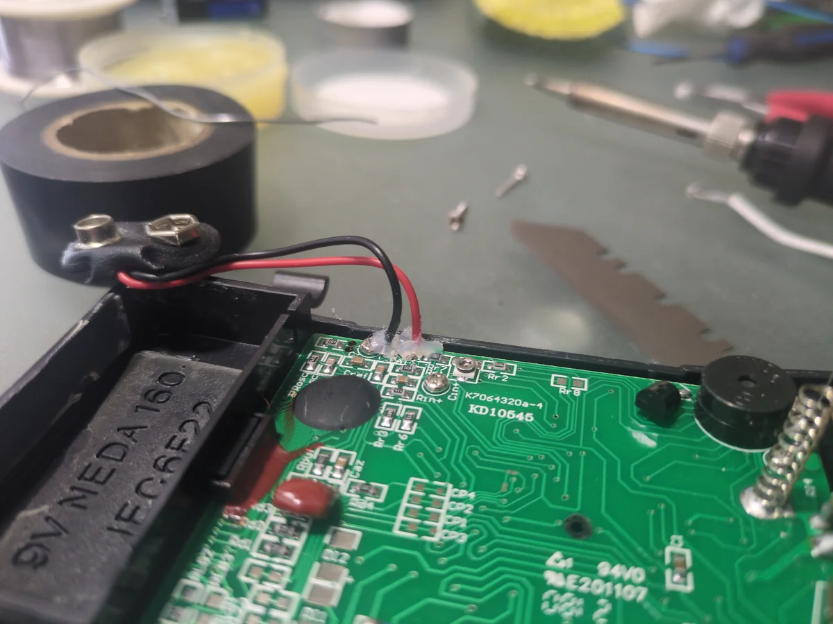
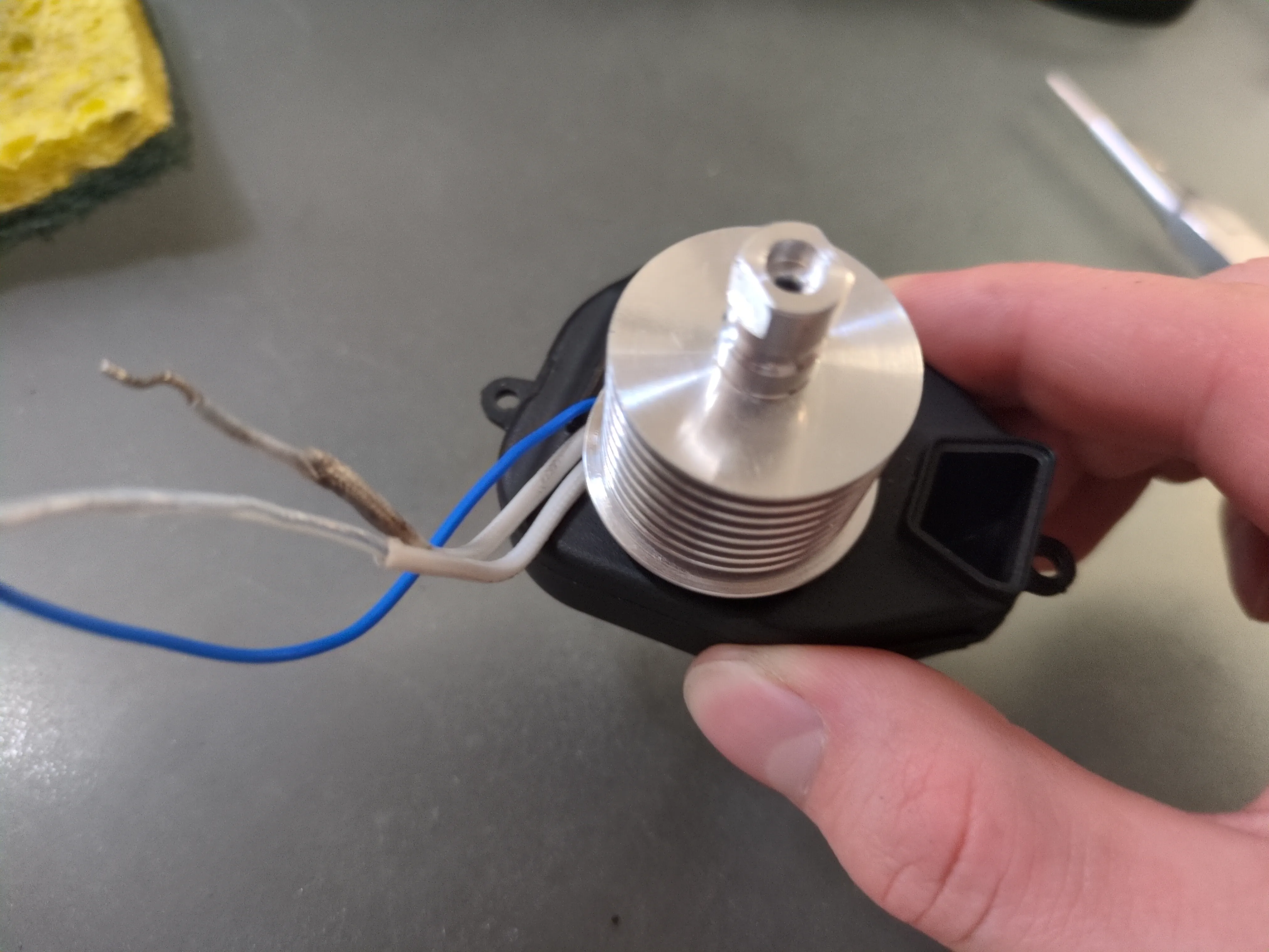
Step 3: Reparing Damaged Wires
Many of the wires from the hotend assembly were broken off. So I soldered them back on and reinforced them with high temp JB weld. The components themselves are still removable if I ever need to replace them, but the wires of the components are NEVER coming off again.
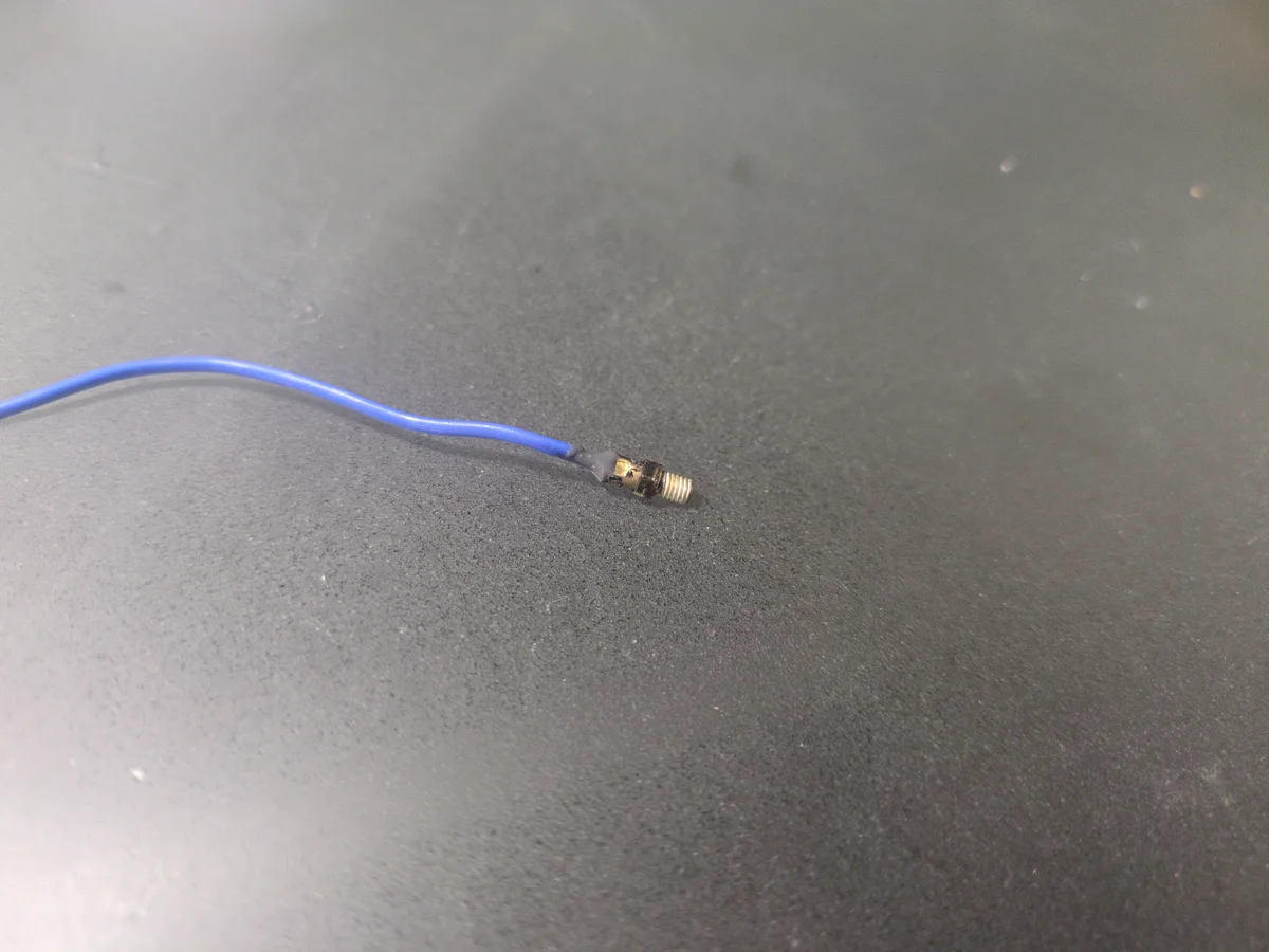
Step 4.1: Testing the Thermocouple (Part 1)
Originally I had assumed that the Dremel 3D45 used a thermistor for temperature sensing. Setting my multimeter to resistor mode, I was getting low resistance readings. My initial thought was that the thermistor was broken or that my multimeter was low on battery (possible since I haven't changed it in years). Before buying a new thermistor, I decided to replace the battery of the multimeter. Just in case.
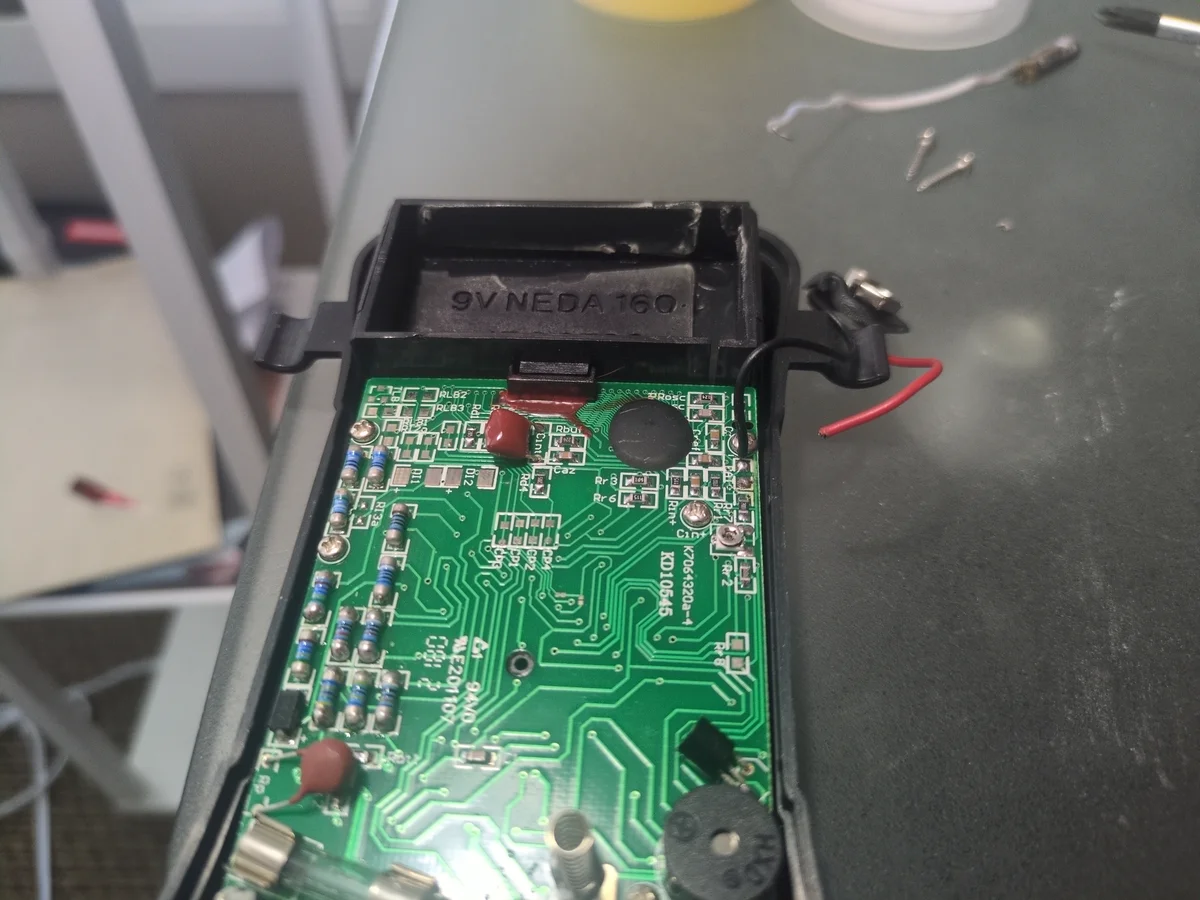
Step 4.2: Reparing the Multimeter
While replacing the battery in my multimeter, I accidentally tore the positive lead wire. These wires looked extremely fragile I was surprised it hadn't broken before. I ended up soldering it back on and using hot glue to keep it from tearing again.
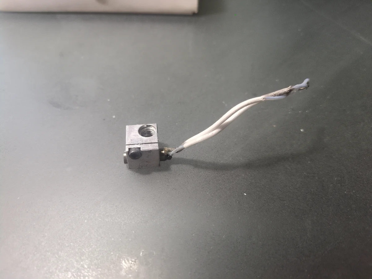
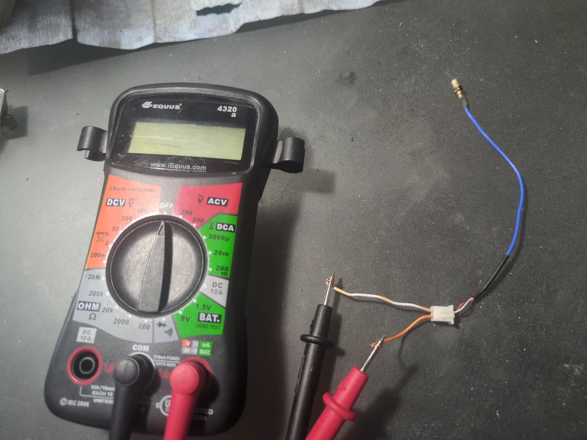
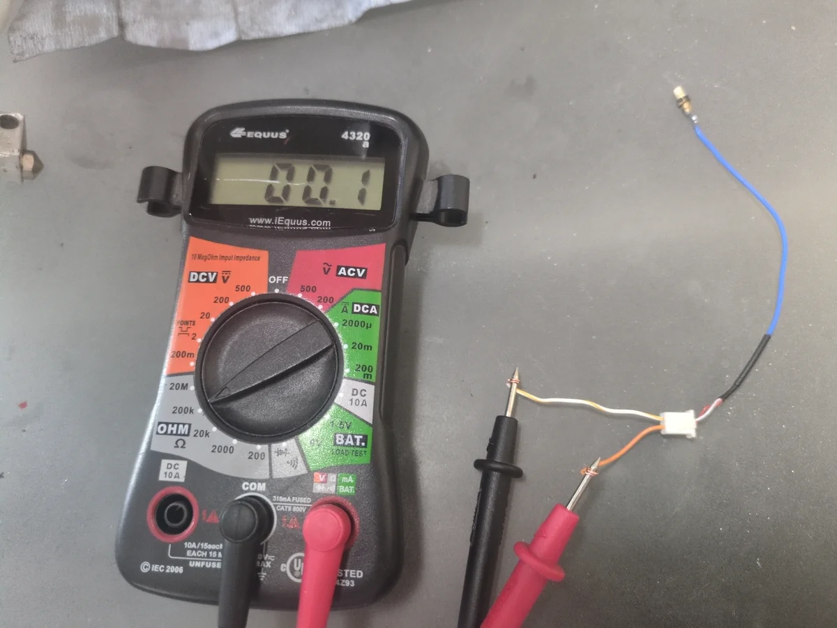
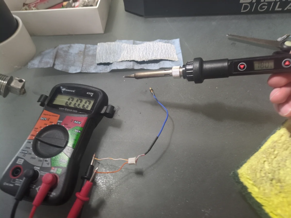
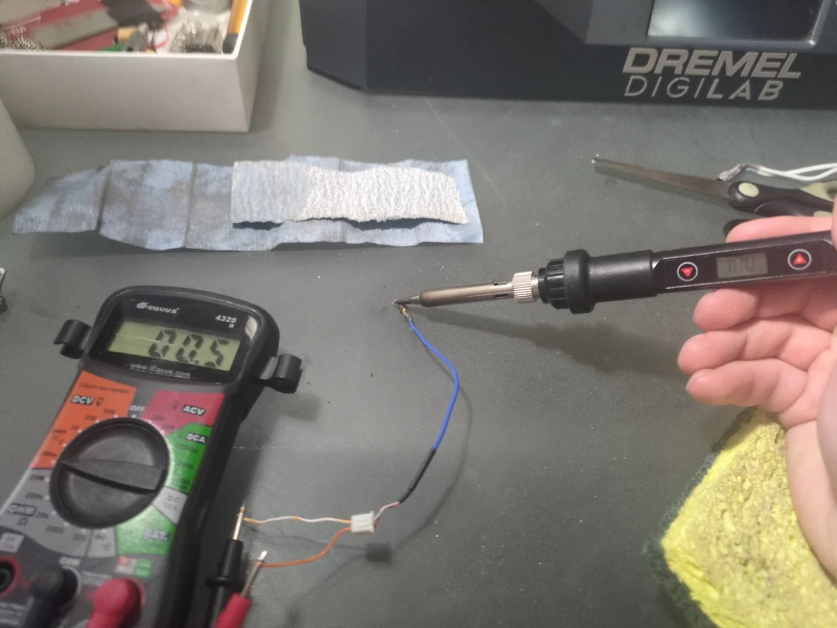
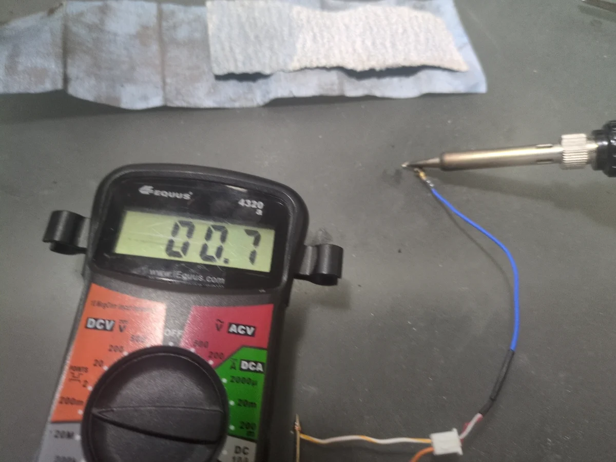
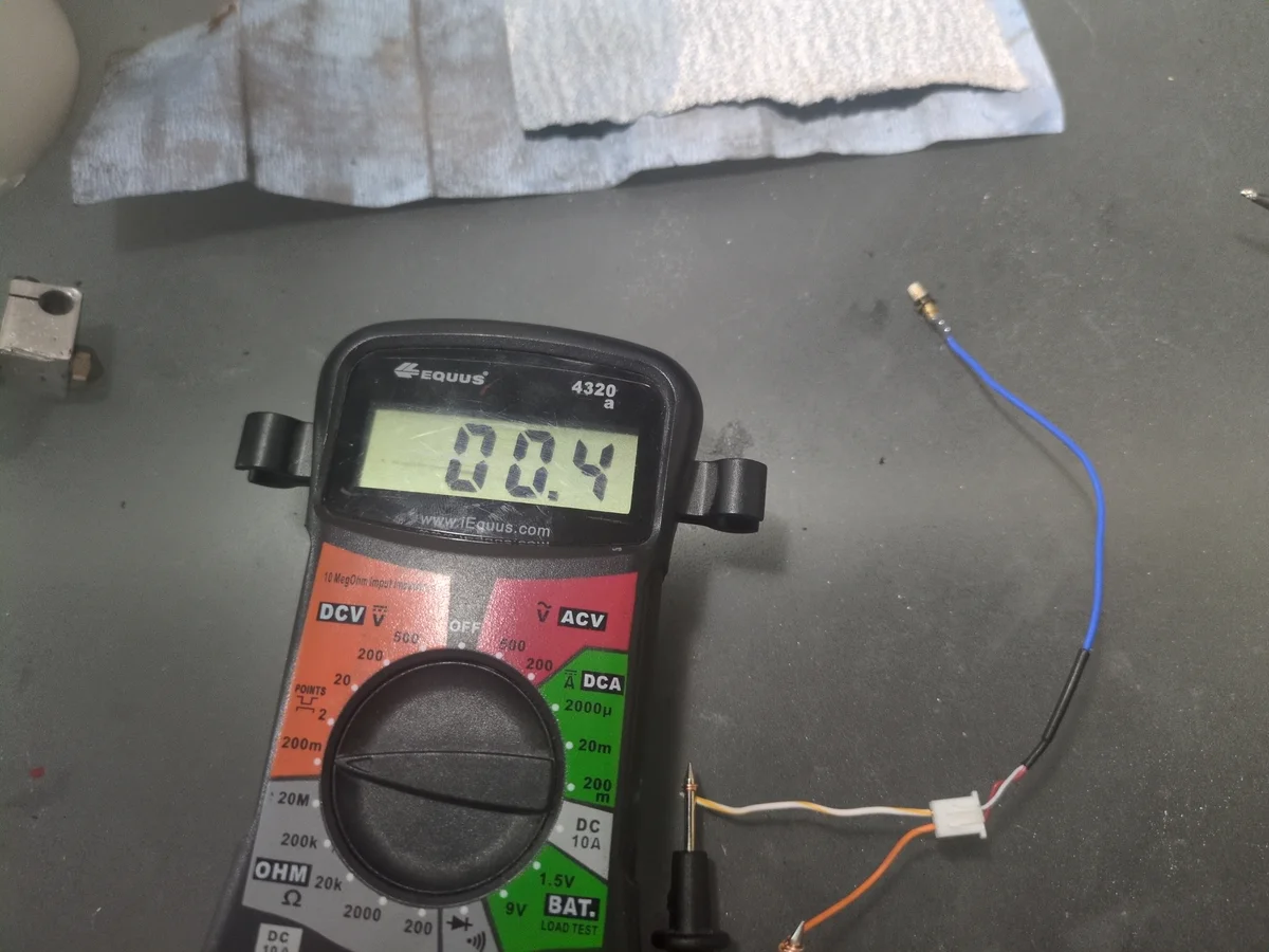
Step 4.3: Testing the Thermocouple (Part 2)
After replacing the batteries of the multimeter, and testing the thermistor again, I was getting very odd readings. However the readings were inconsistent with a broken thermistor. Specifically I noticed that it seemed to flip polarity from positive resistance to negative resistance just on its own. I researched online and found that this was actually because it was a thermocouple, not a thermistor. So setting the multimeter to measure low voltage DC, and gently using a soldering iron on low temp, I was able to get the readings of a working thermocouple. Meaning I would not be replacing this part.
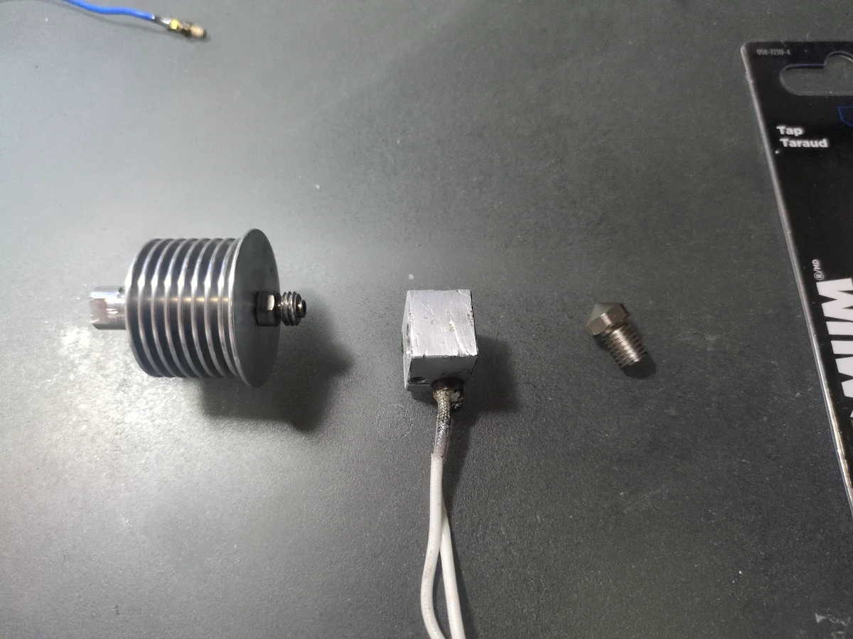
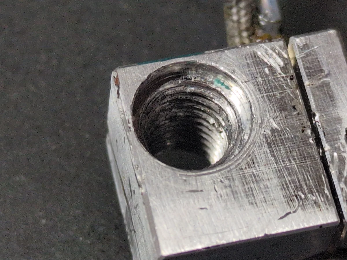
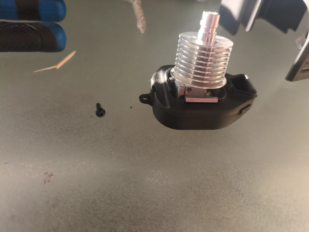
Step 5: Heat Block Assembly Issue
With the arrival of the new nozzle, I attempted to assemble the hotend. However, I quickly discovered the threads inside the heat block were severely damaged. It was impossible to screw the nozzle and the heat sink back together securely. The proprietary nature of the Dremel printer meant that finding a replacement heat block was impossible and I would have to replace the entire hotend assembly. Instead, I decided to retap the threads. I identified the thread size as 8mm-1.25 and purchased a tap to clean up and restore the internal threads.
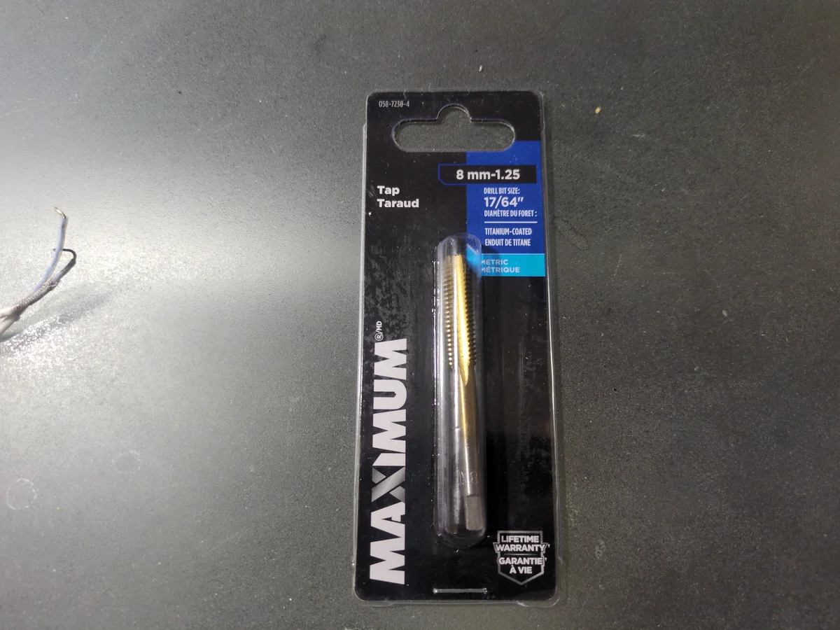
Step 6: Retapping the Heat Block
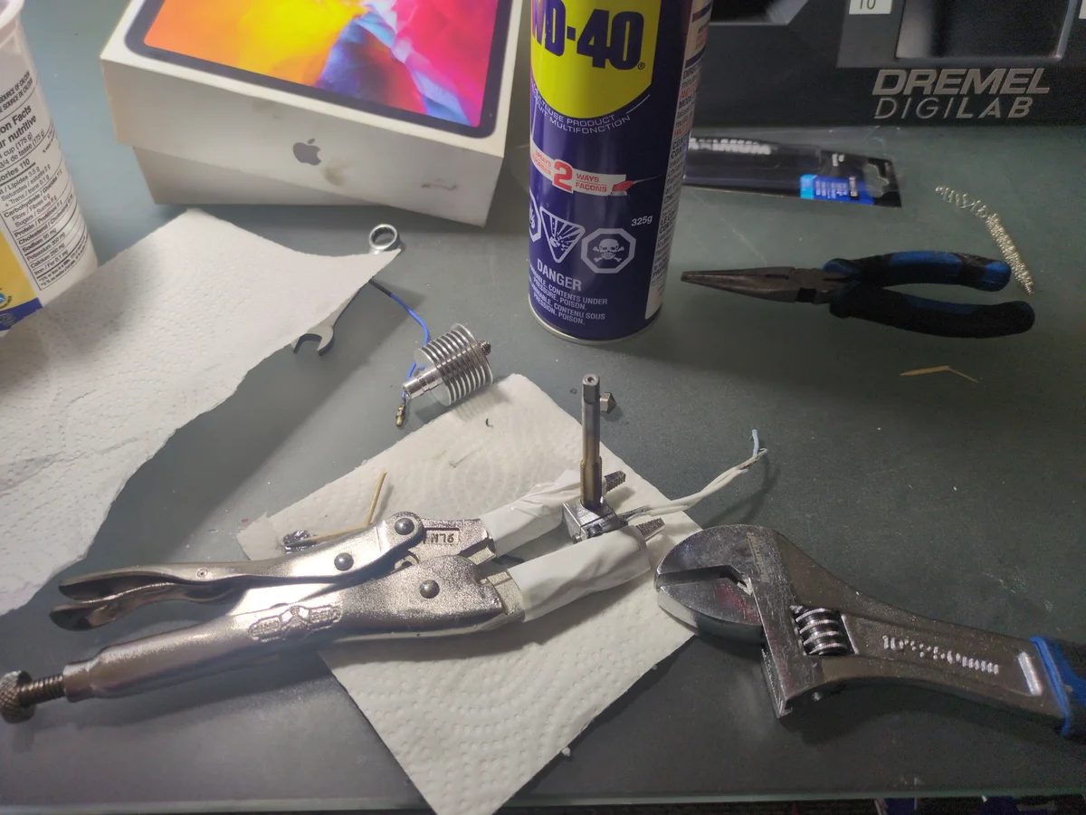
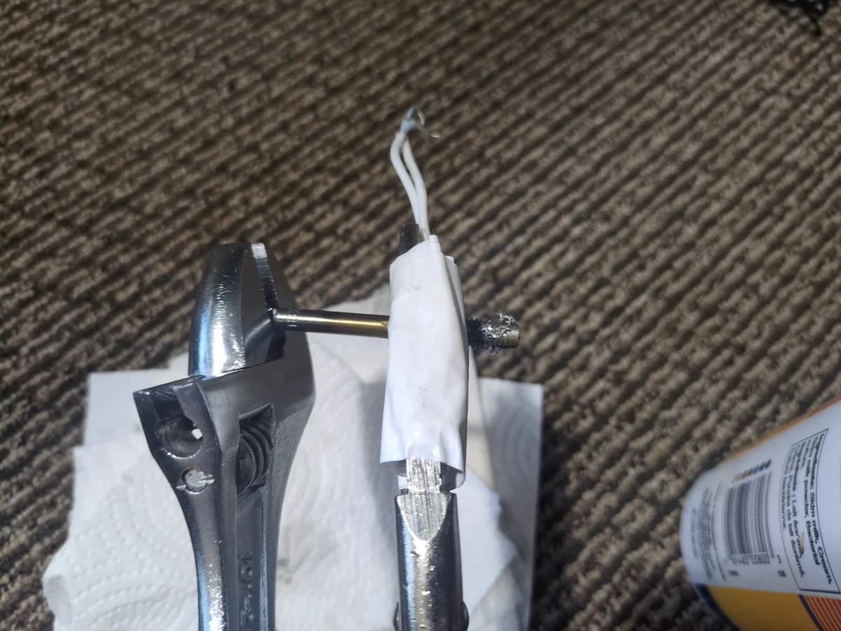
Before tapping, I would highly recommend finding a vice to hold the heat block securely. I did not have one so rather than buying one, I found that stepping on a pair of duct tape wrapped vice grips worked well enough to hold the heat block. This was my first experience using a tap and I was not sure how much force to apply. I started by applying gentle pressure and slowly increasing it until I felt the tap bite into the threads. Every step felt like it was going to break the tap or the block, but it held up and applying WD-40, I was able to successfully restore the threads.
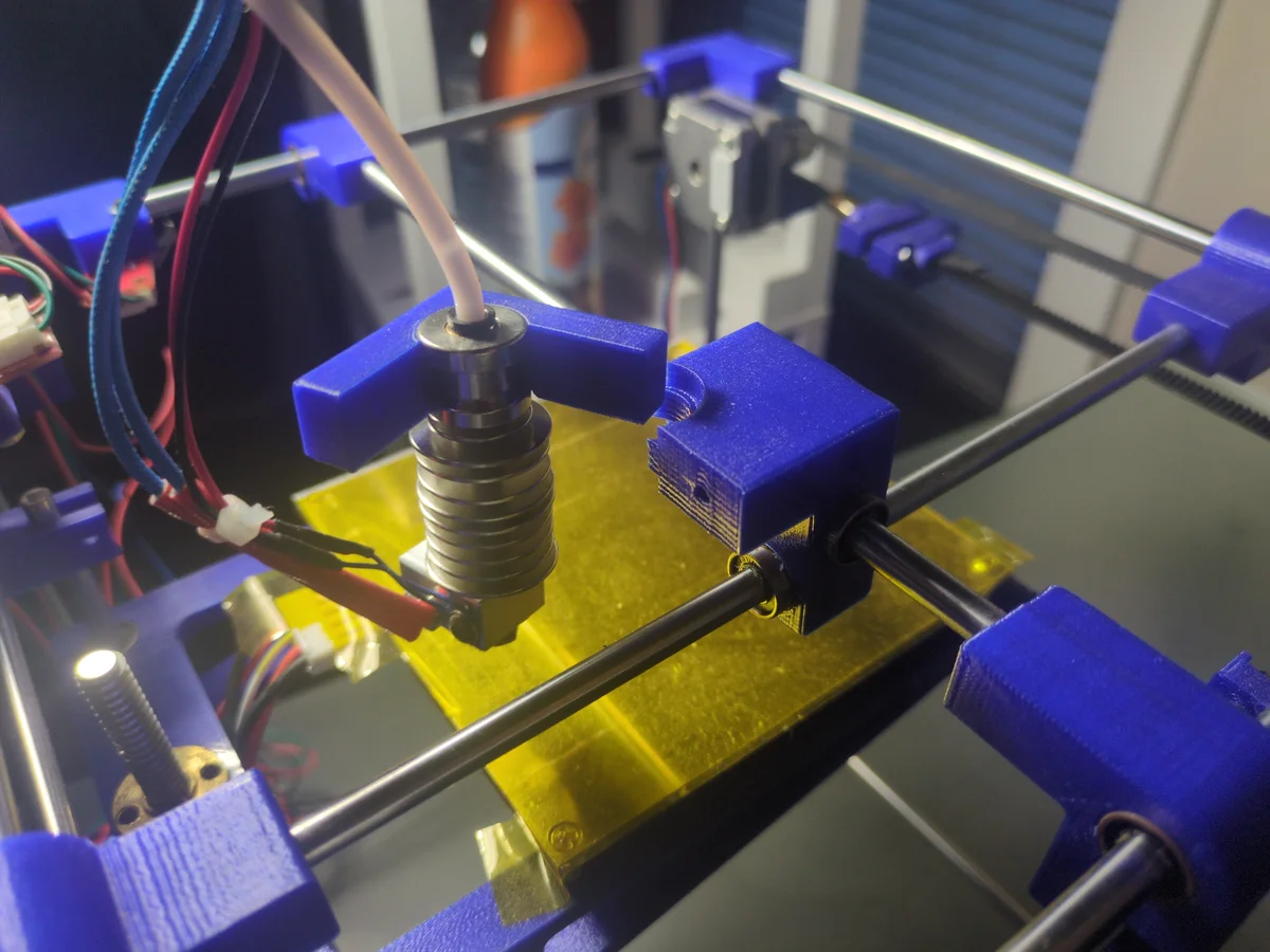
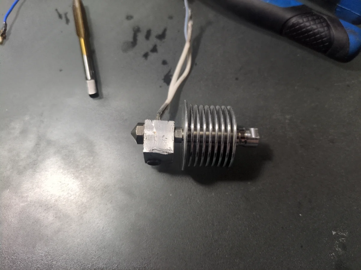
After retapping the threads, I was able to screw the nozzle and heat sink back together securely. I then reassembled the hotend and noticed it was very slightly angled. I worried the precision required for a 3D printer would exacerbated this issue, so hoped that I could calibrate and compensate for the discrepency later. In the worst case, I would just buy a new hotend completely. This issue actually never came up and I have not had any problems with the hotend since.
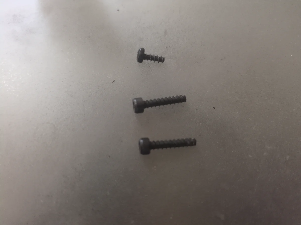
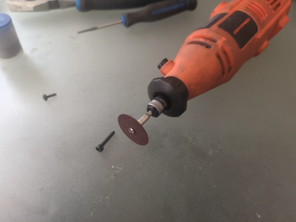
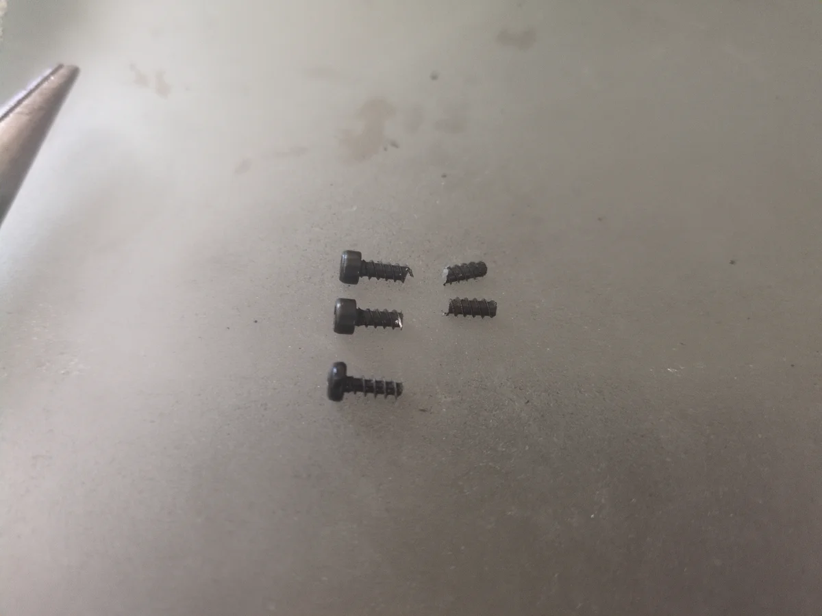
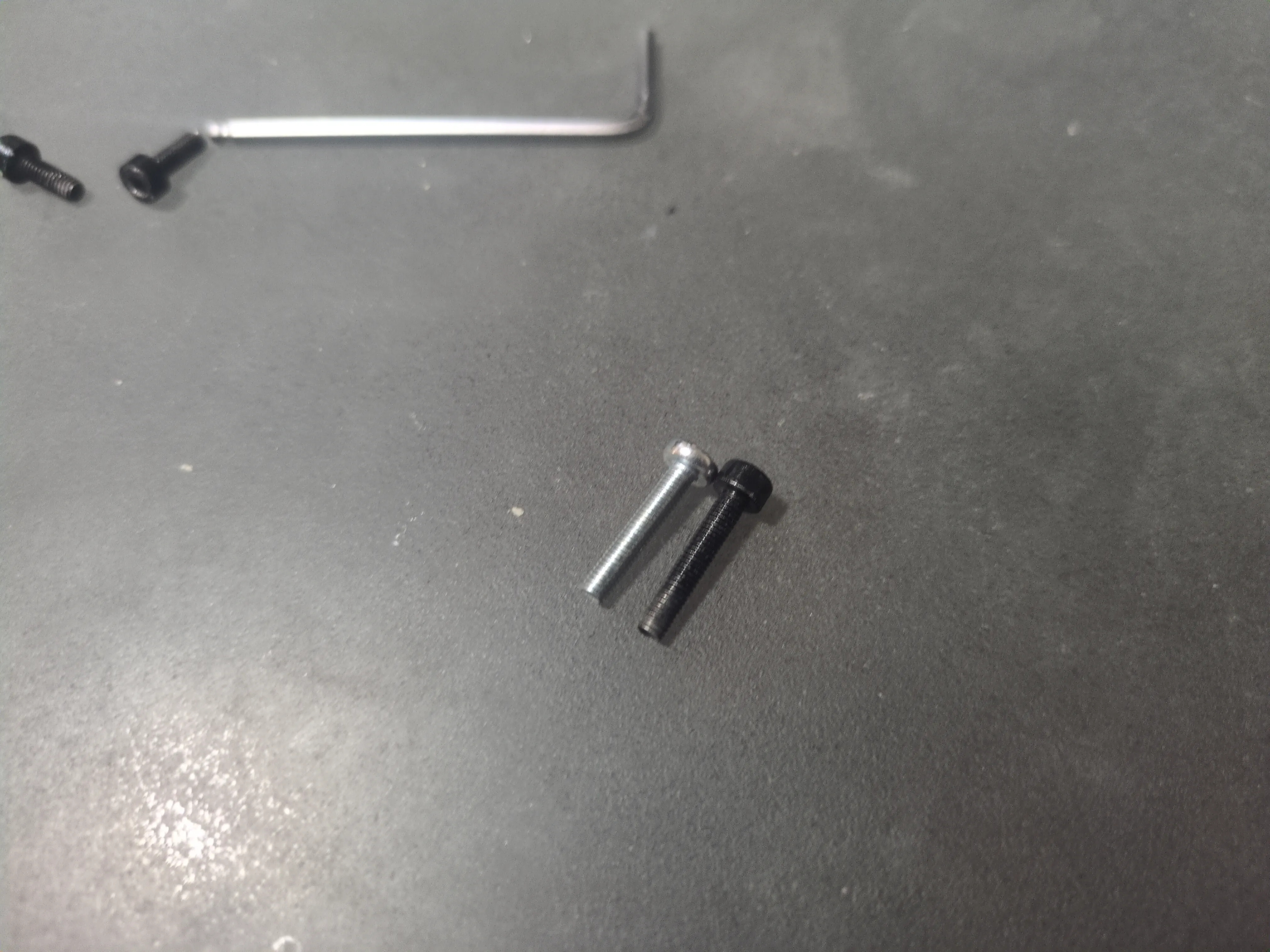
Step 7: Custom Screw Fabrication
During reassembly, I realized I was missing a critical screw needed to attach the hotend to the printer frame. After searching multiple hardware stores, I found it extremely difficult to find an exact replacement that matched the required diameter, length, and thread spacing. I eventually found two screws with the correct diameter and thread pitch (almost), but they were twice the length. To make them work, I decided to cut them down to the precise length using a dremel with a cutting wheel.
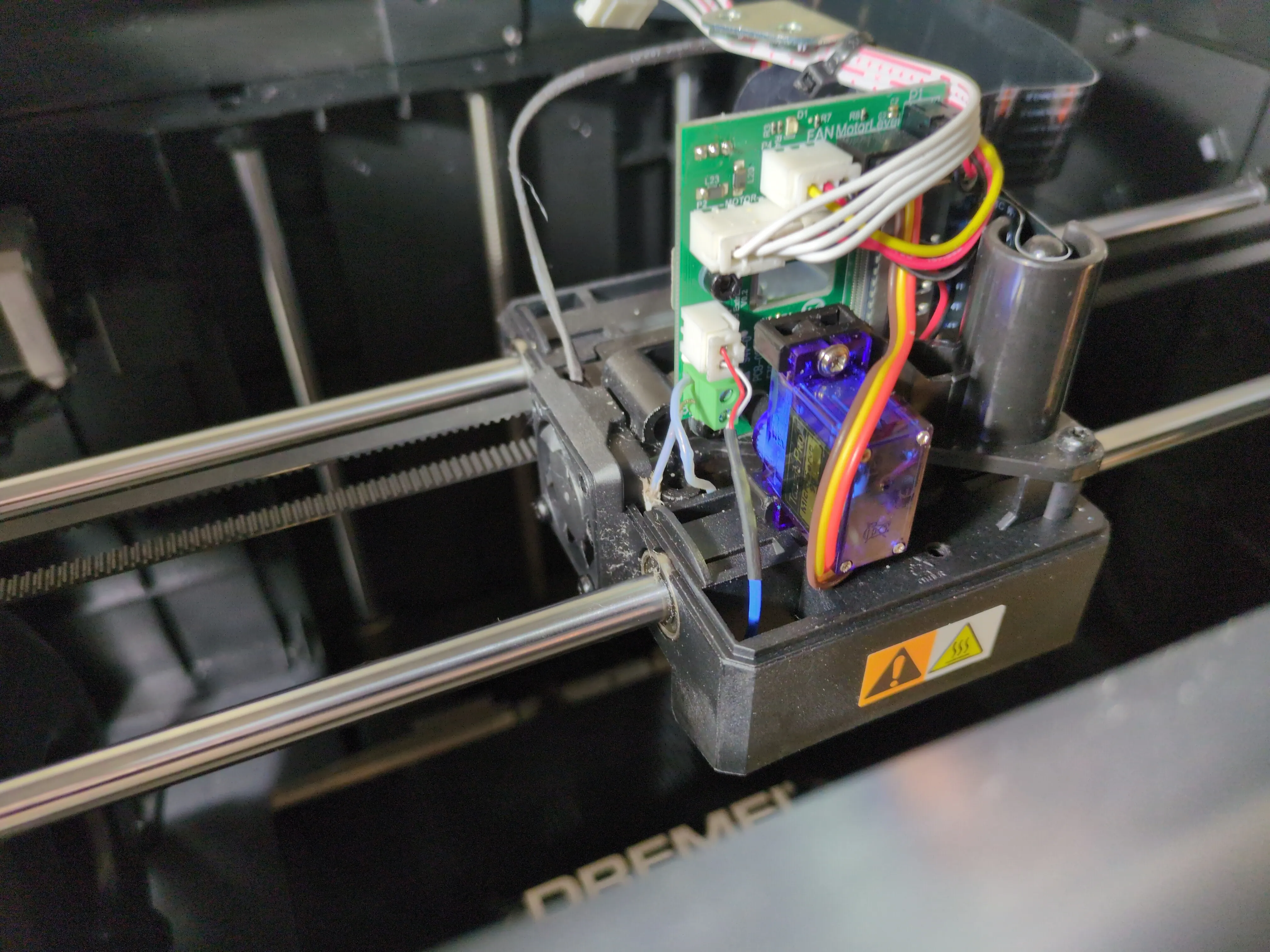
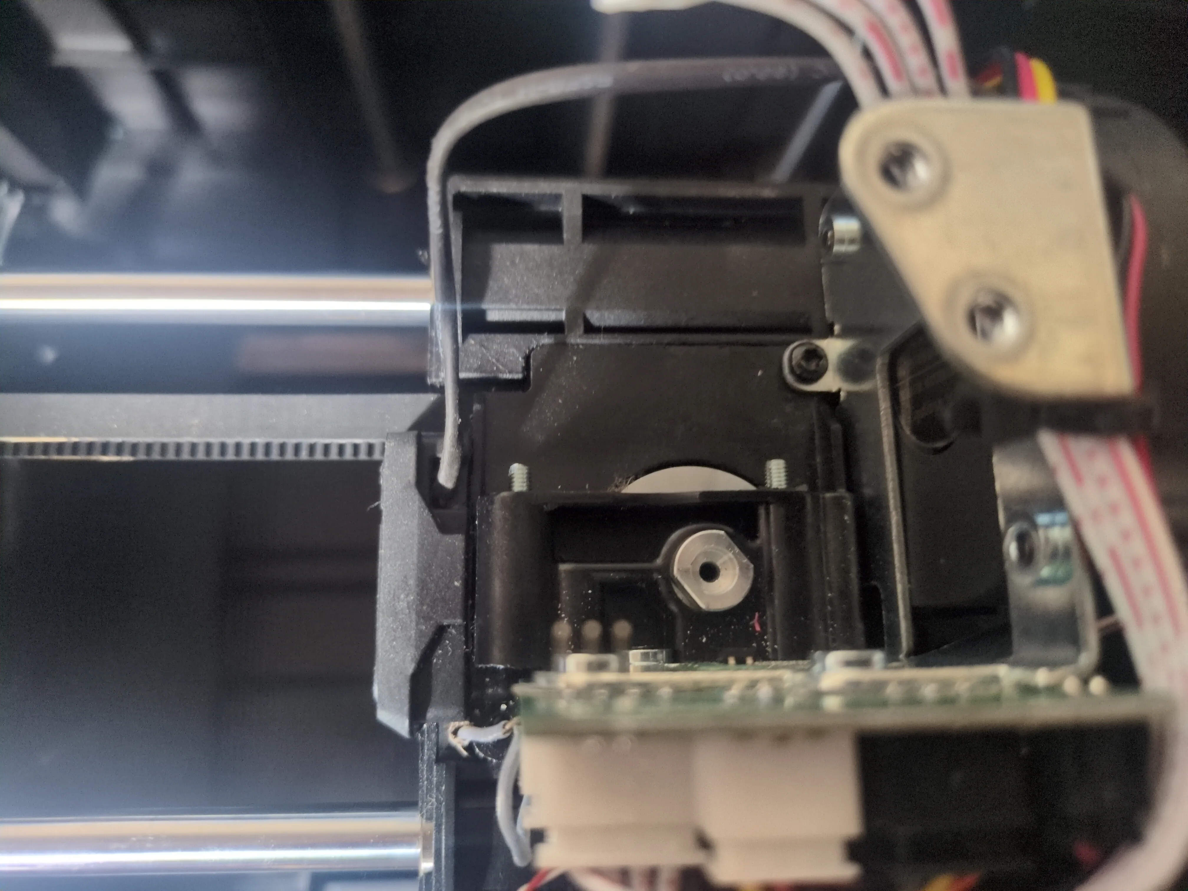
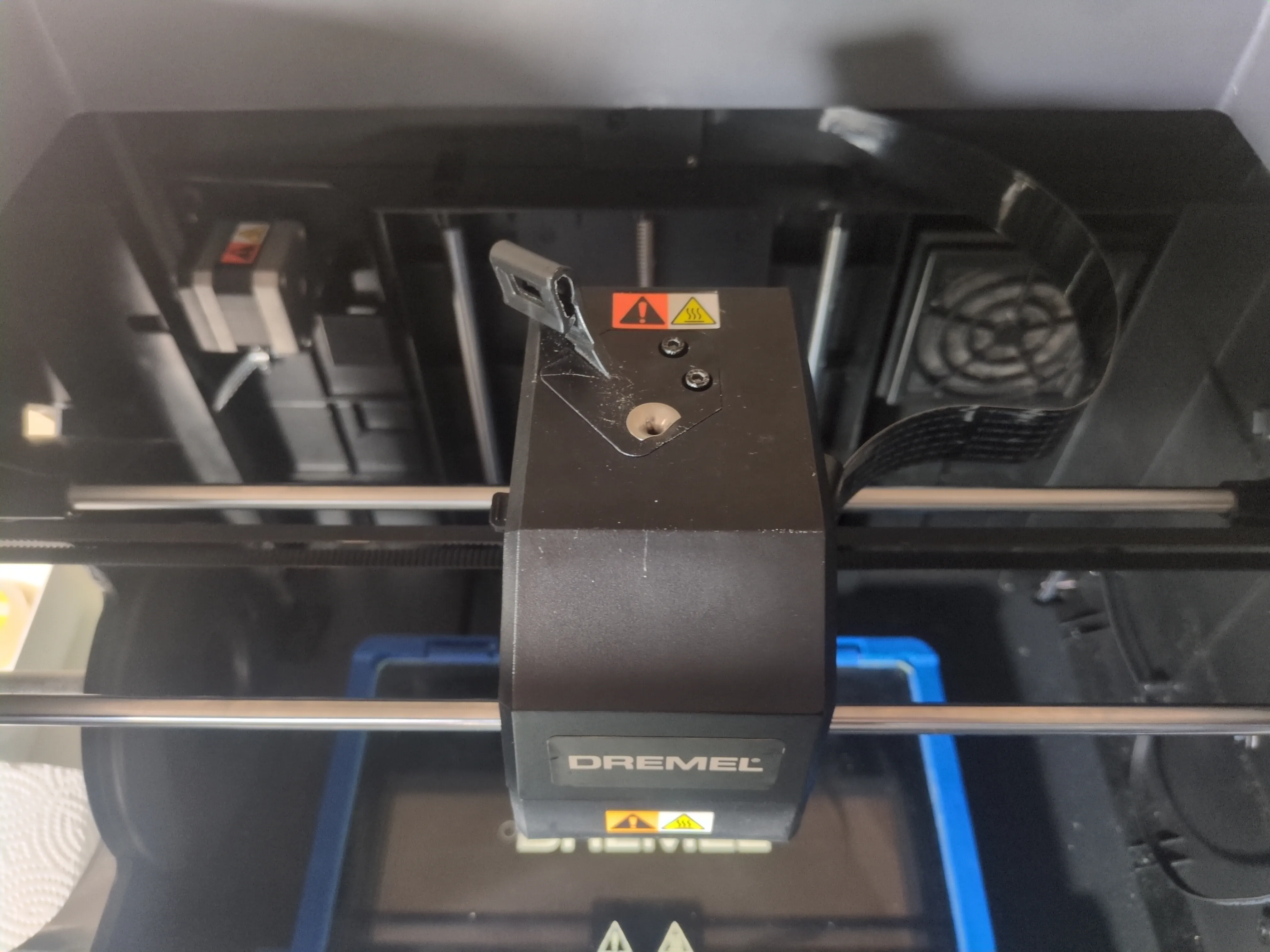
Step 8: Wiring & Casing Alignment
With the internal components coming together, I focused on the wiring path. It was crucial to align the wires perfectly along the designated gap in the casing to ensure a flush fit. I performed a test fit by routing the wires up through the gaps to the circuit board above. This allowed me to verify the connections and clearance before finally securing the casing in place and completing the electrical routing to the board.
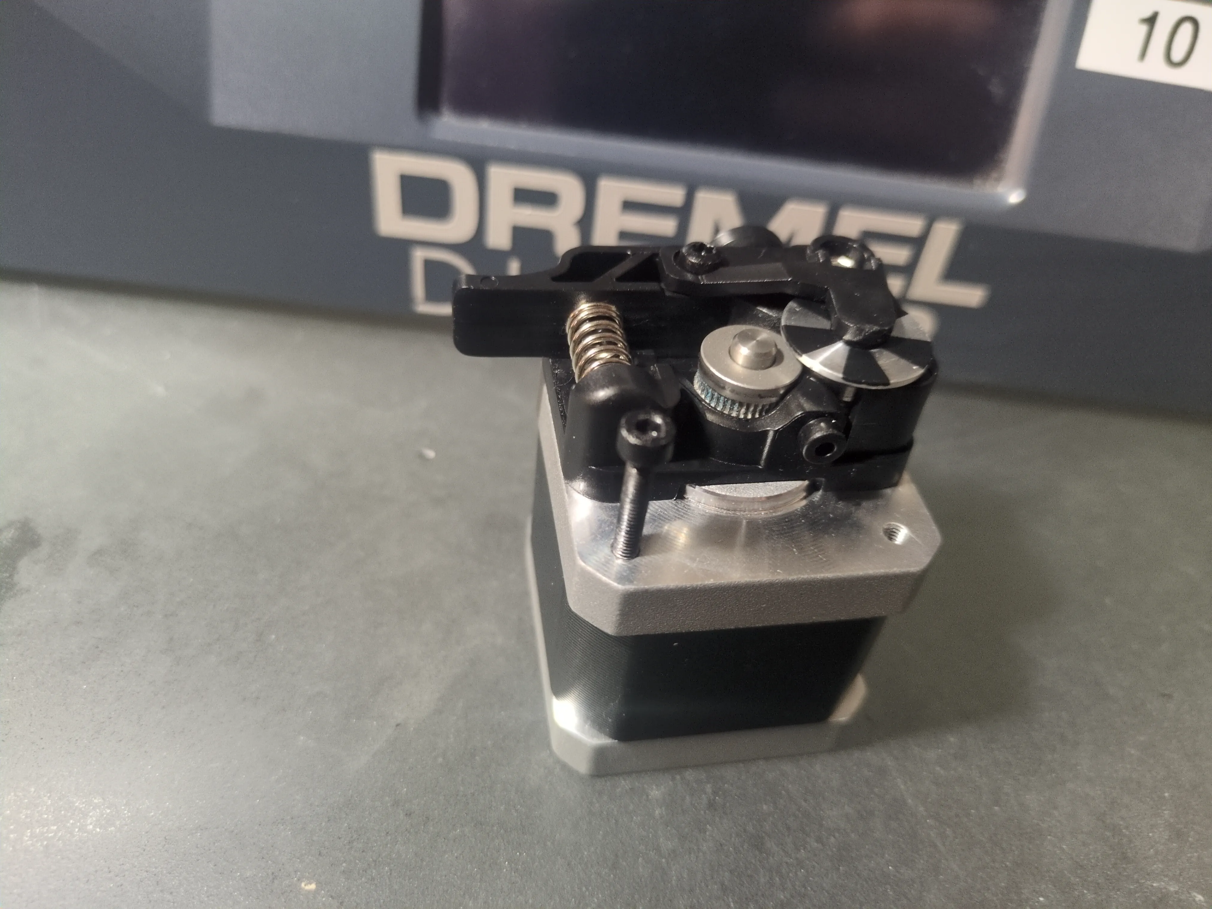
Step 9: Filament Feeding Motor & Screw Match
Next was the filament feeding motor. I realized I was again missing another screw. Luckily, I was able to find a screw with the exact same dimensions from a local hardware store. Even the head size was the same which was perfect for the clearance required. With the correct screws, I was finally able to mount the filament feeding motor and secure it firmly in place.
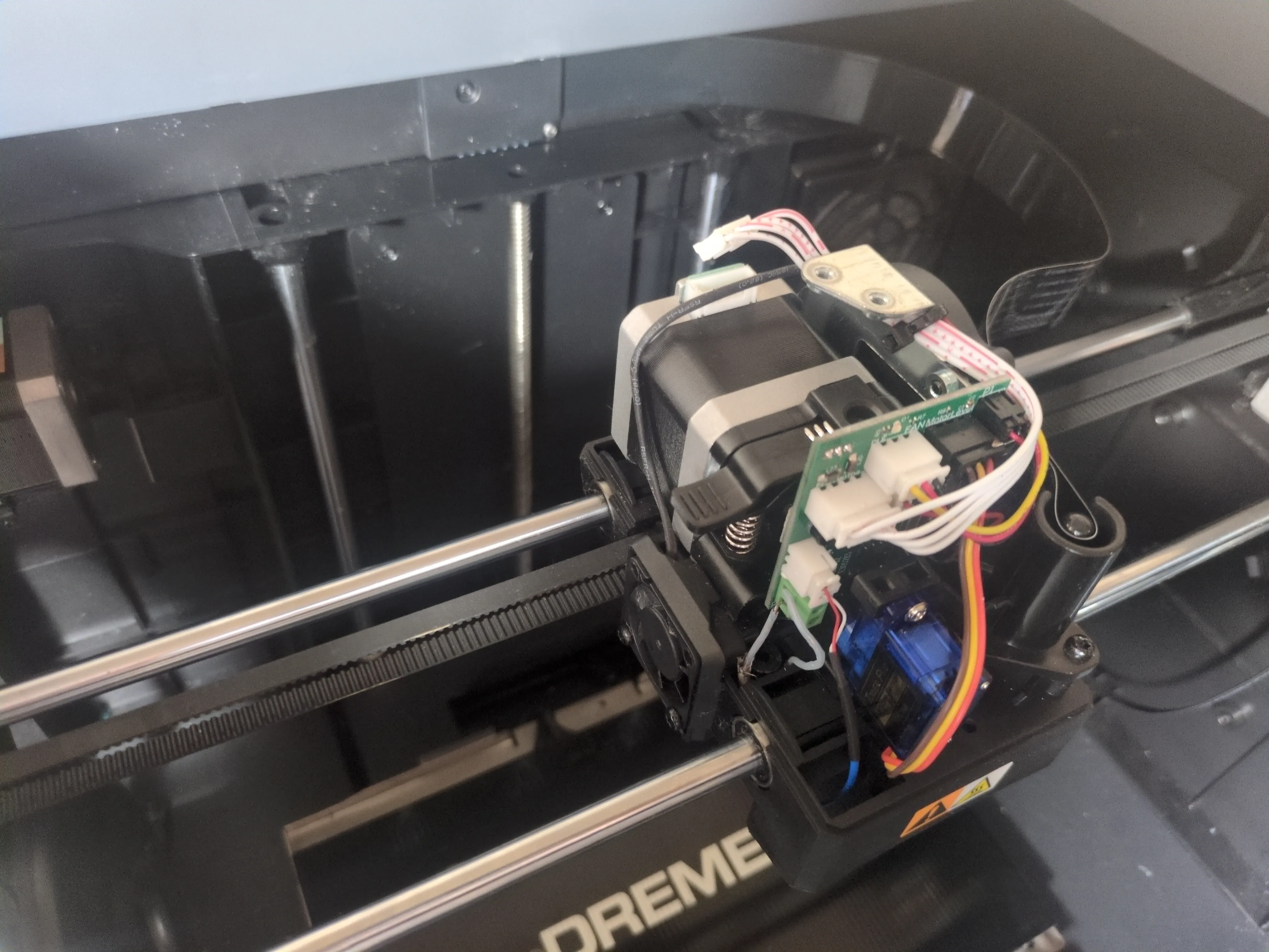
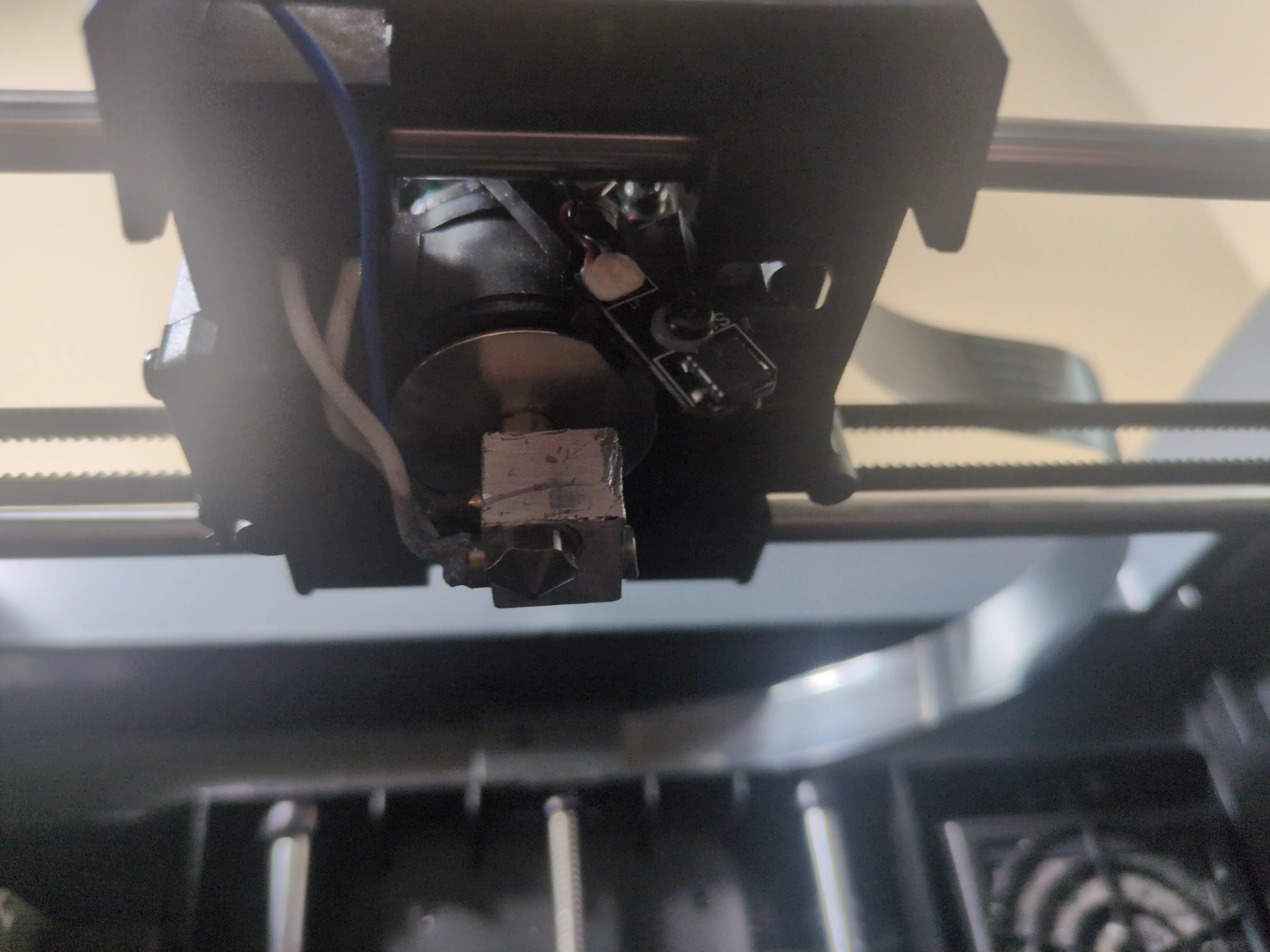
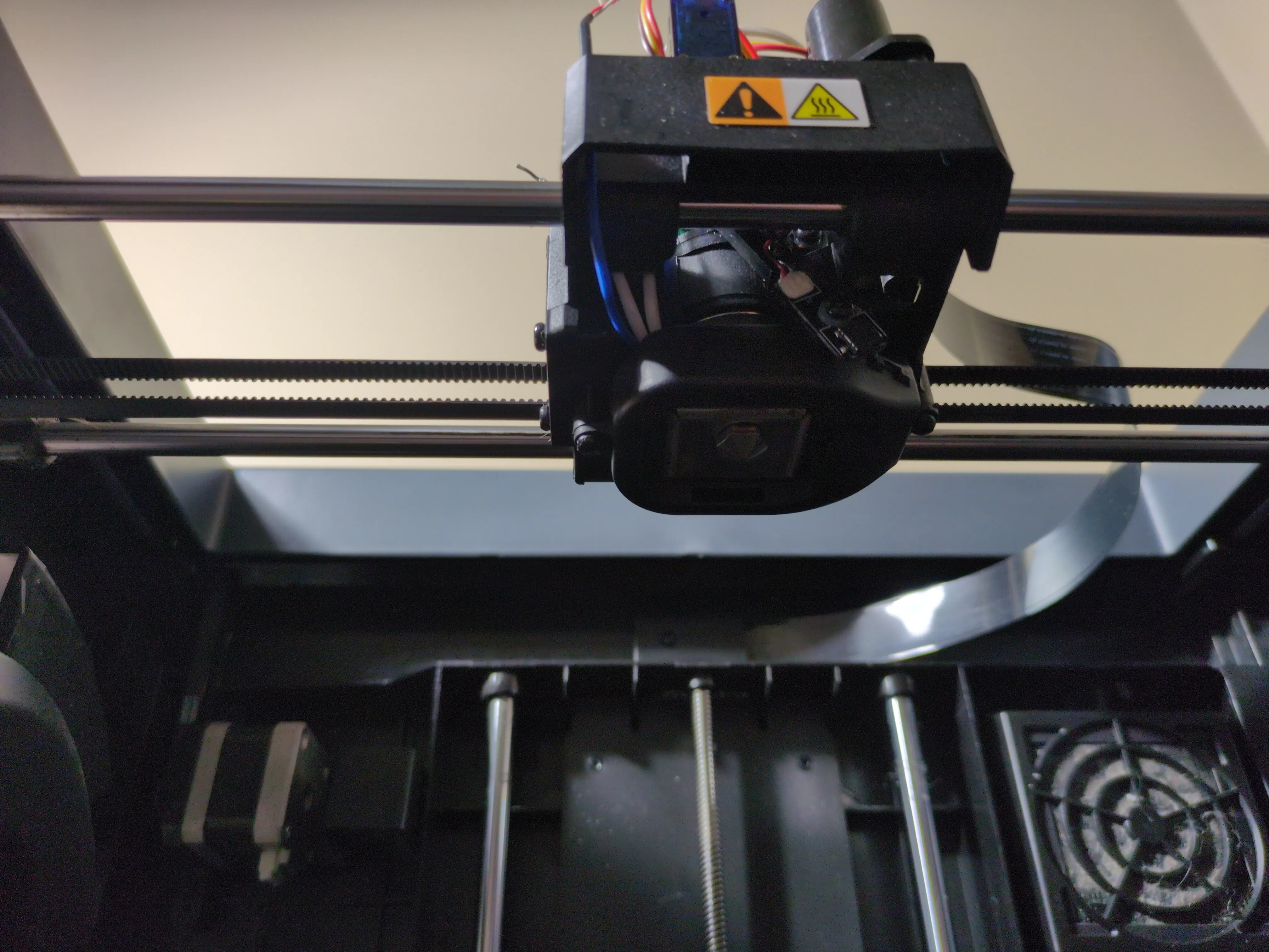
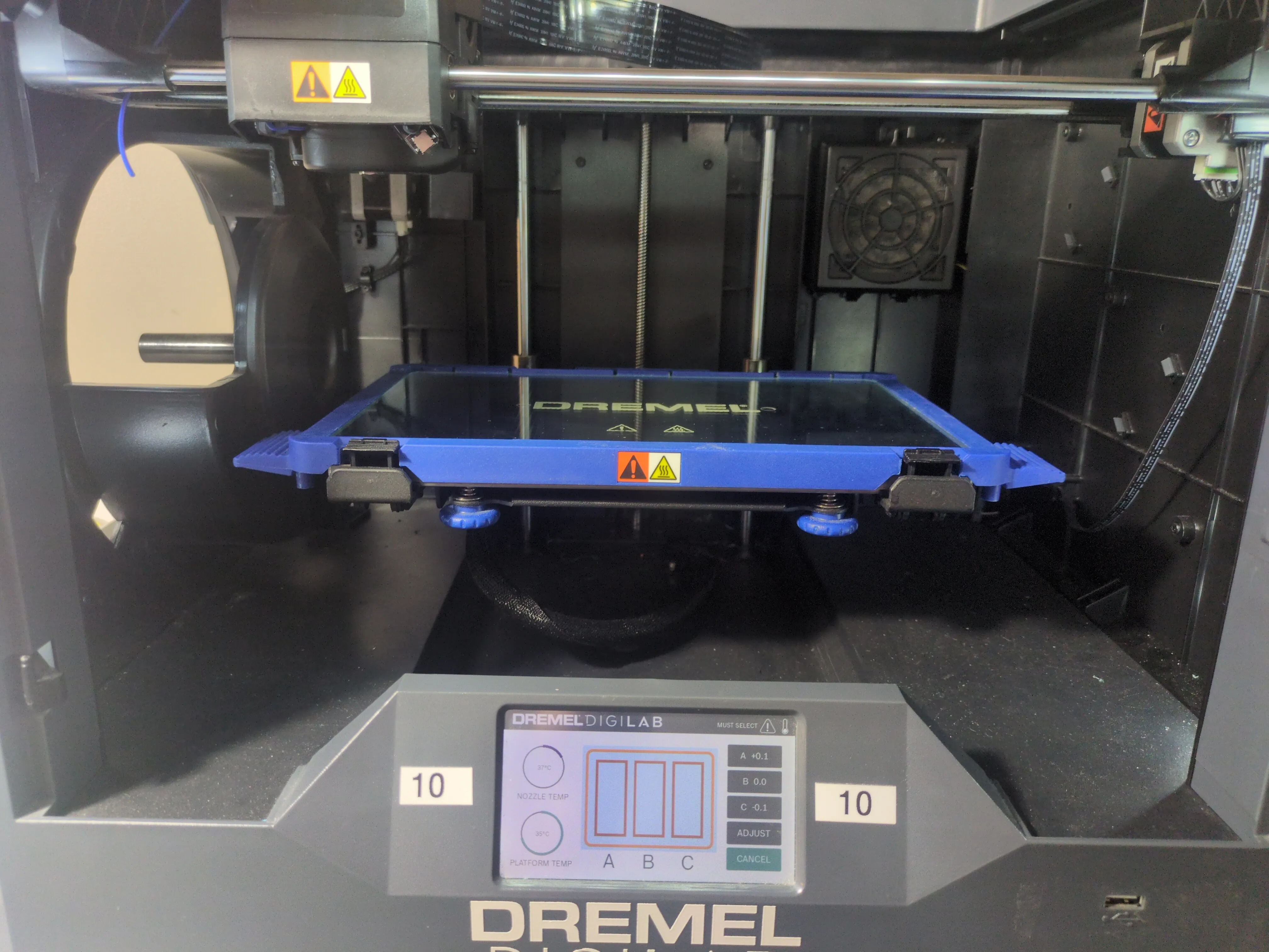
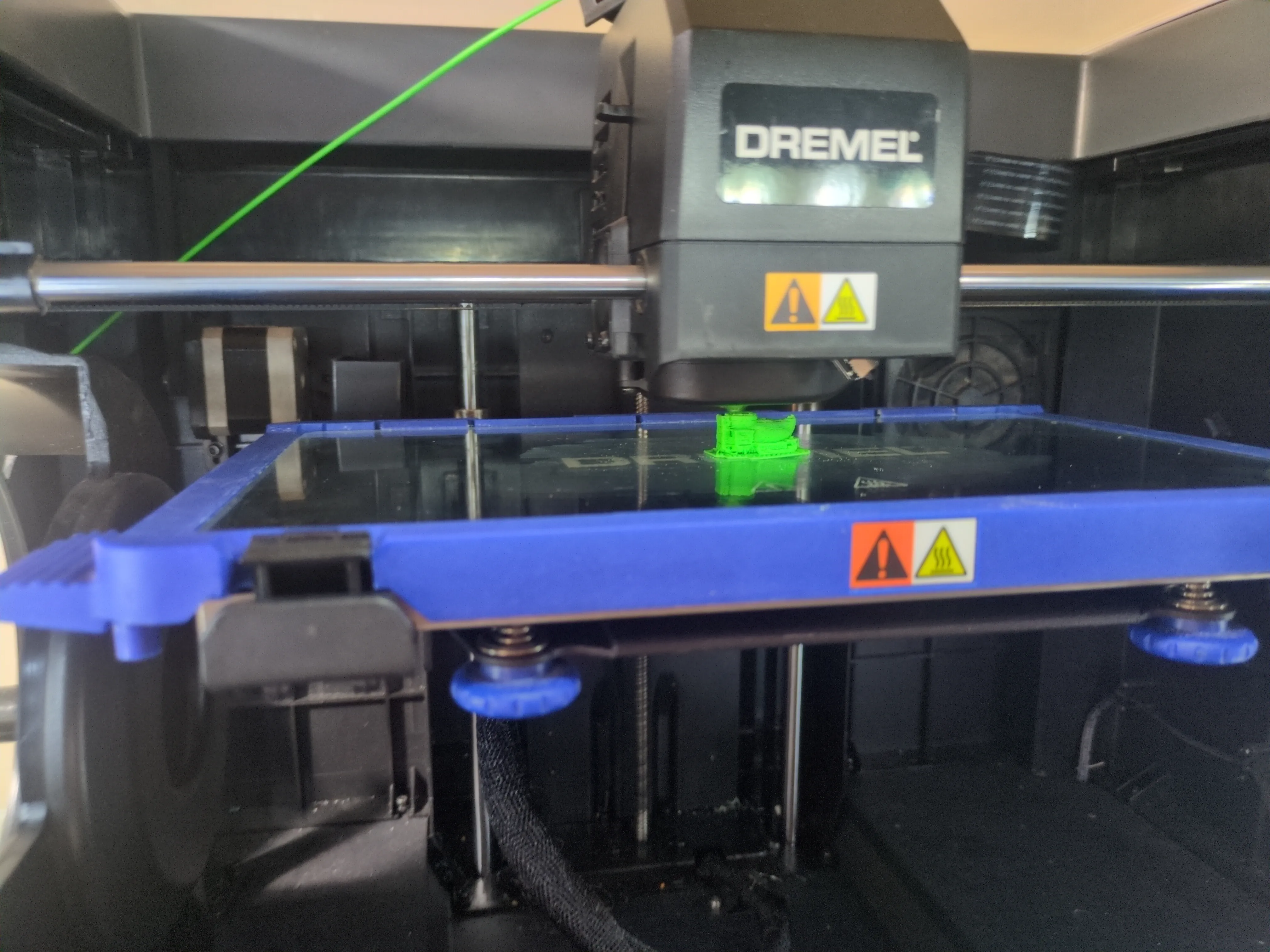
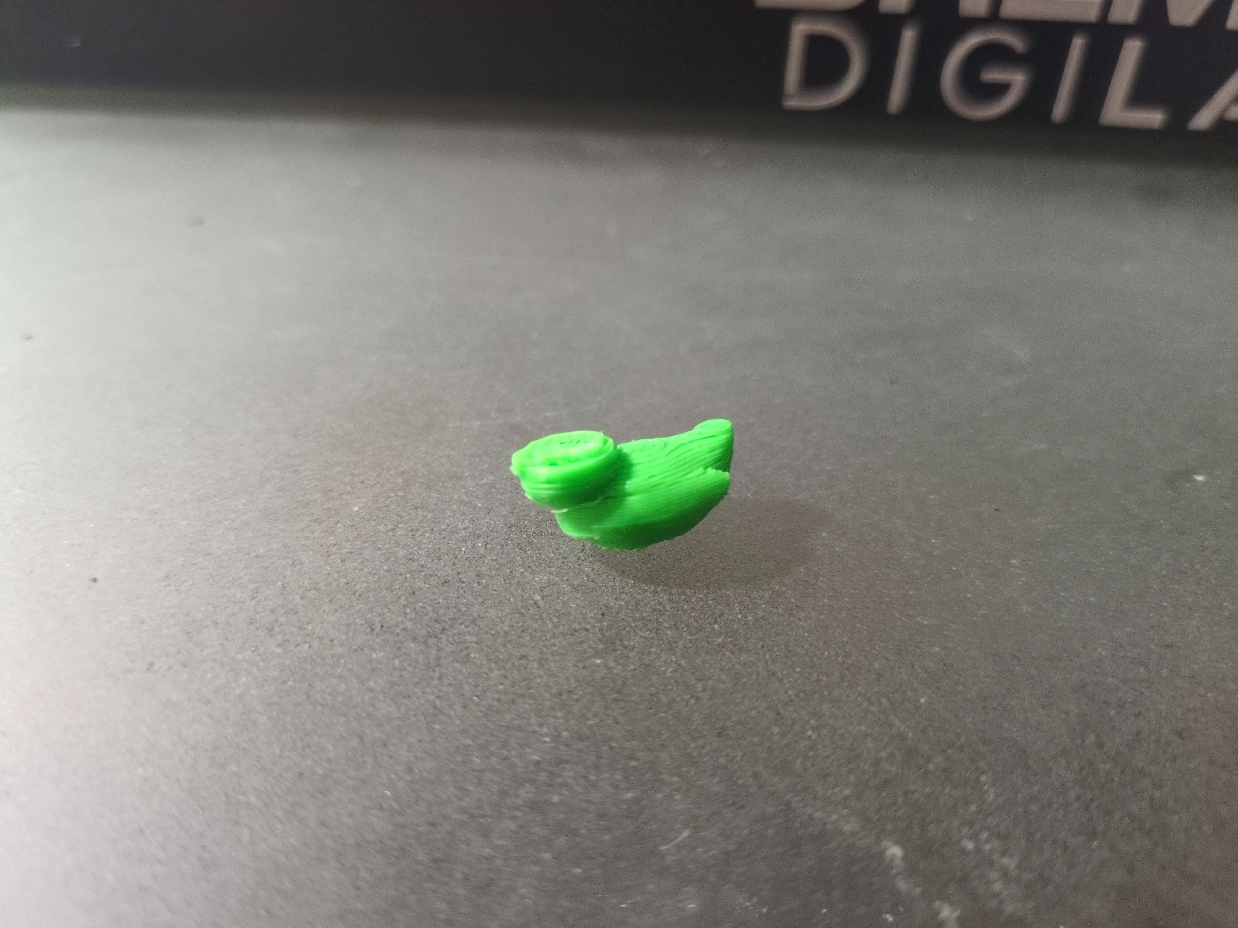
Step 10: Final Reassembly & Initial Test Run
With all the individual components restored and the wiring secured, I reached the complete reassembly milestone. After attaching the last pieces, I moved on to the calibration and setup phase, ensuring the bed was level and the offsets were correct. The moment of truth came with the first test run. I chose a small minifigure rubber ducky as the test subject. While the printer is now fully operational, the first print showed some issues. Half the head was missing and the layer height was atrocious. Additionally, I found dremels glass bed + glue stick combo is not the best for adhesion which was extremely frustratingly inconsistent. This confirms the printer is working, but it is now ready for the next phase of deep calibration, optimization, and modifications to achieve perfect print quality.
Closing Thoughts
This restoration journey has been a challenging yet rewarding process of troubleshooting, fabrication, and precision assembly. This was the first time I had ever attempted to repair a 3D printer, and seeing it power on, calibrate, and successfully execute its first test run marks a major milestone. While the "mangled" rubber ducky shows that there is still significant work to be done in terms of tuning and potential modifications, the core machine is now fully functional. The foundation is set for continuous optimization, and I look forward to pushing this Dremel 3D45 to its full potential.