Remote Control Car
Robotics, Electrical, and Mechanical Engineering for Students Grades 8/9

While working at DiscoverE engineering camp at the University of Alberta I was tasked with creating the curriculum for a remote control car project. The challenge was to create a car that could be built in a single day by students grades 8 and 9 with minimal tools and materials.
This project combines mechanical and electrical engineering to create a functional RC car from scratch. Designed for students and hobbyists, it focuses on teaching core concepts like torque, gear ratios, and RF (Radio Frequency) transmission while keeping the total cost under $10.
Project Overview
Materials
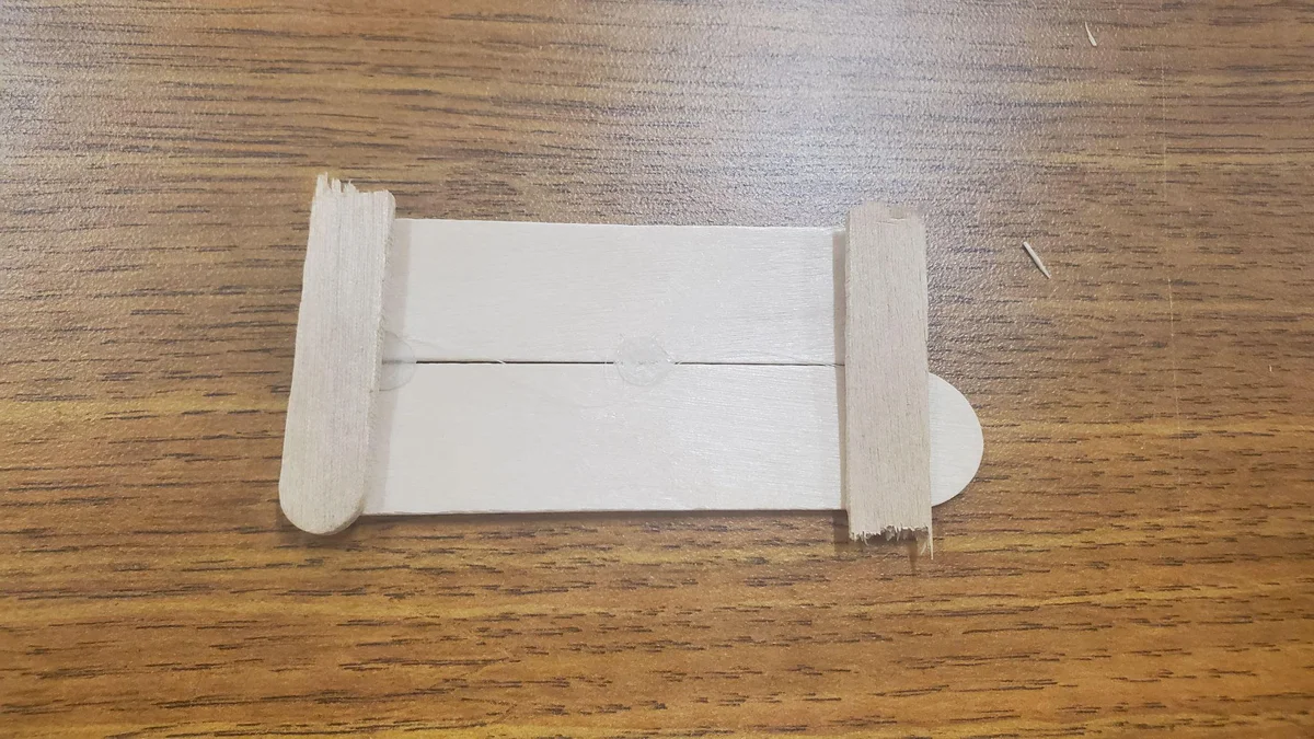
- 4 Jumbo Popsicle Sticks
- 2 Thin Skewers (2.5mm dia)
- 4 Wheels (42mm dia)
- 3V DC Motor
- 2 AA Batteries + Holder
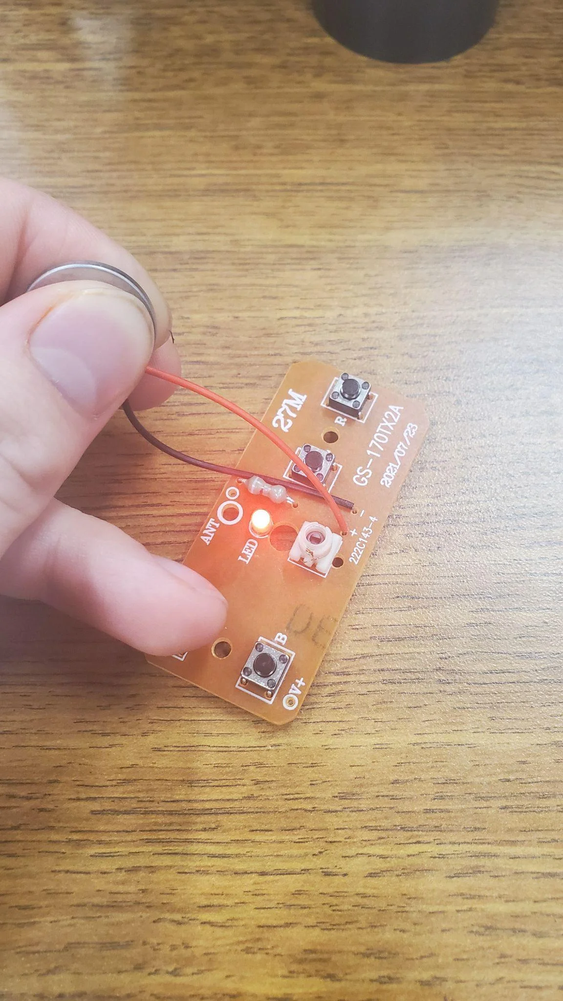
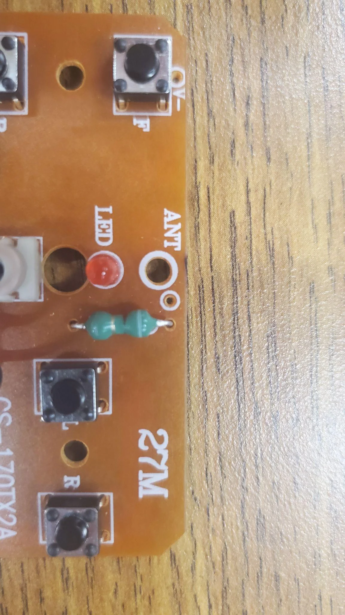
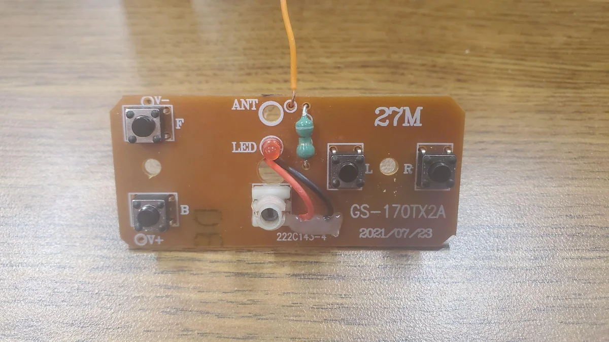
- RF Receiver & Transmitter Circuits (GS-170TX2A)
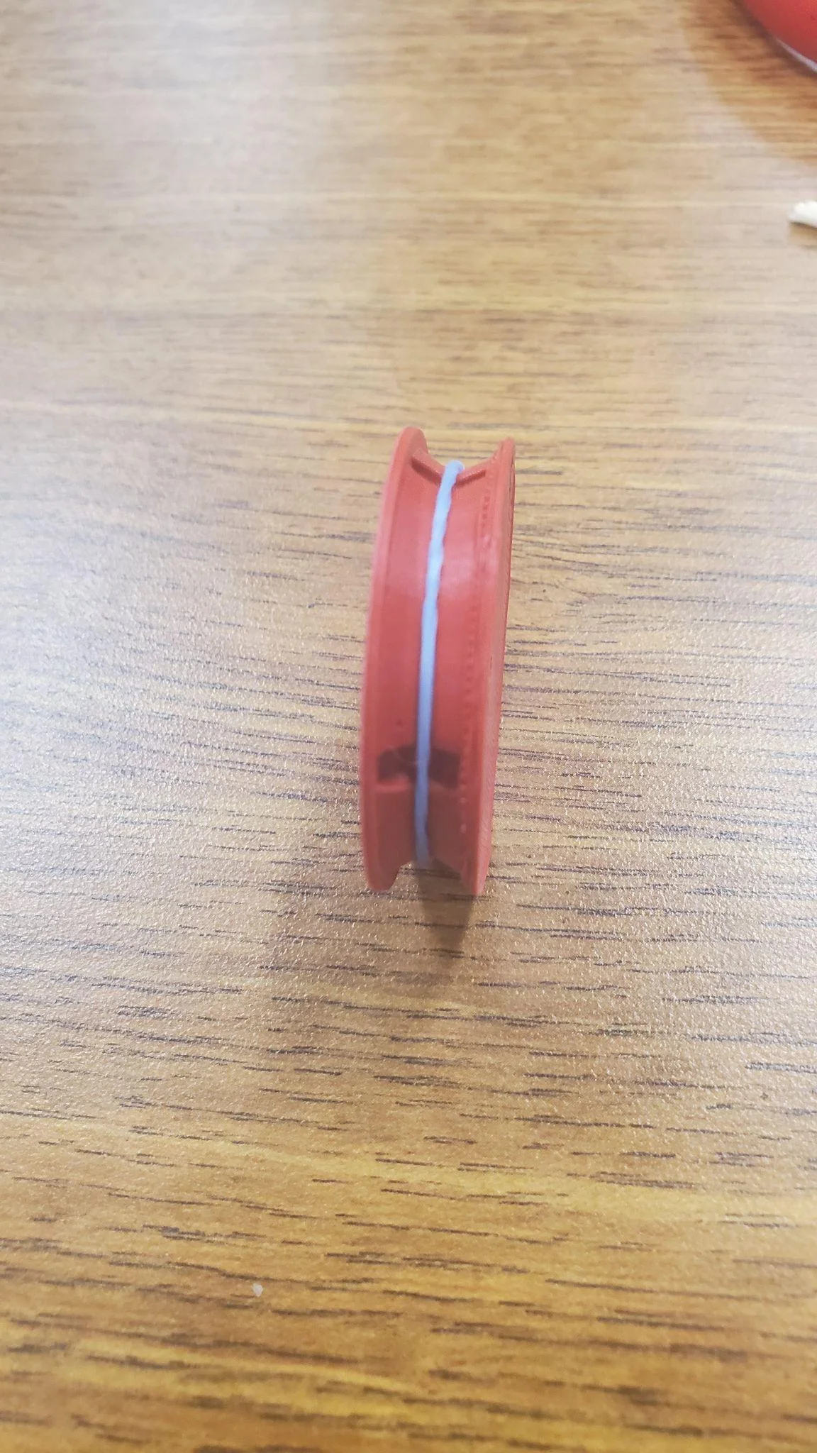
- 3D Printed Gears (Drive & Stopper)
- 1 Regular Straw & 1 Bubble Tea Straw
- Loom Band Elastics
- Googly Eyes (Optional)
- Tools: Ruler, Wire Strippers, Scissors, Hot Glue
Quick Stats
- Target Cost: ~$9.36
- Build Time: ~3.5 Hours
- Complexity: Level 1 (Beginner)
- Required: 3D Printer
- Required: Soldering Iron (Semi-Optional)
Demo Video
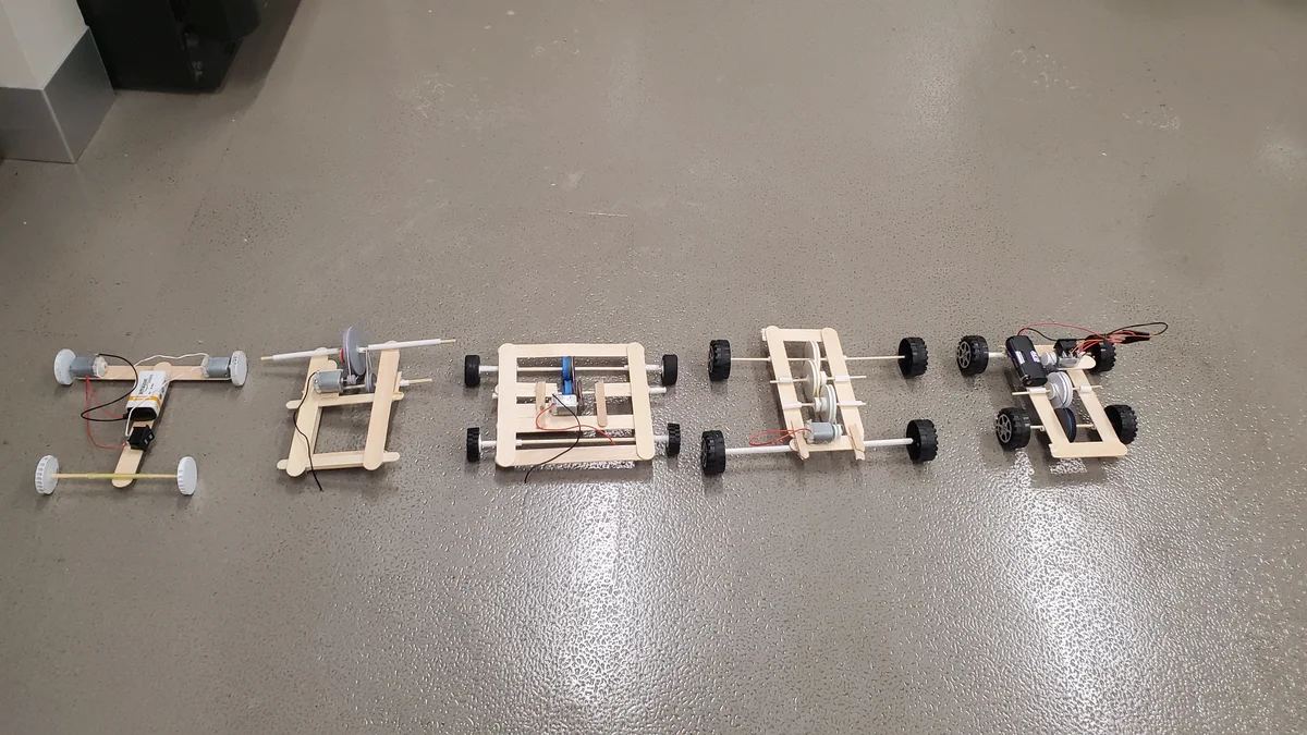
Prototypes
The final design was the result of 6 major iterations, refining chassis stability and axle friction to ensure a reliable build that could be completed by students within the camp timeframe.
3D Print Files
Download the STL files for the custom drive gears.
Part 1: The Car
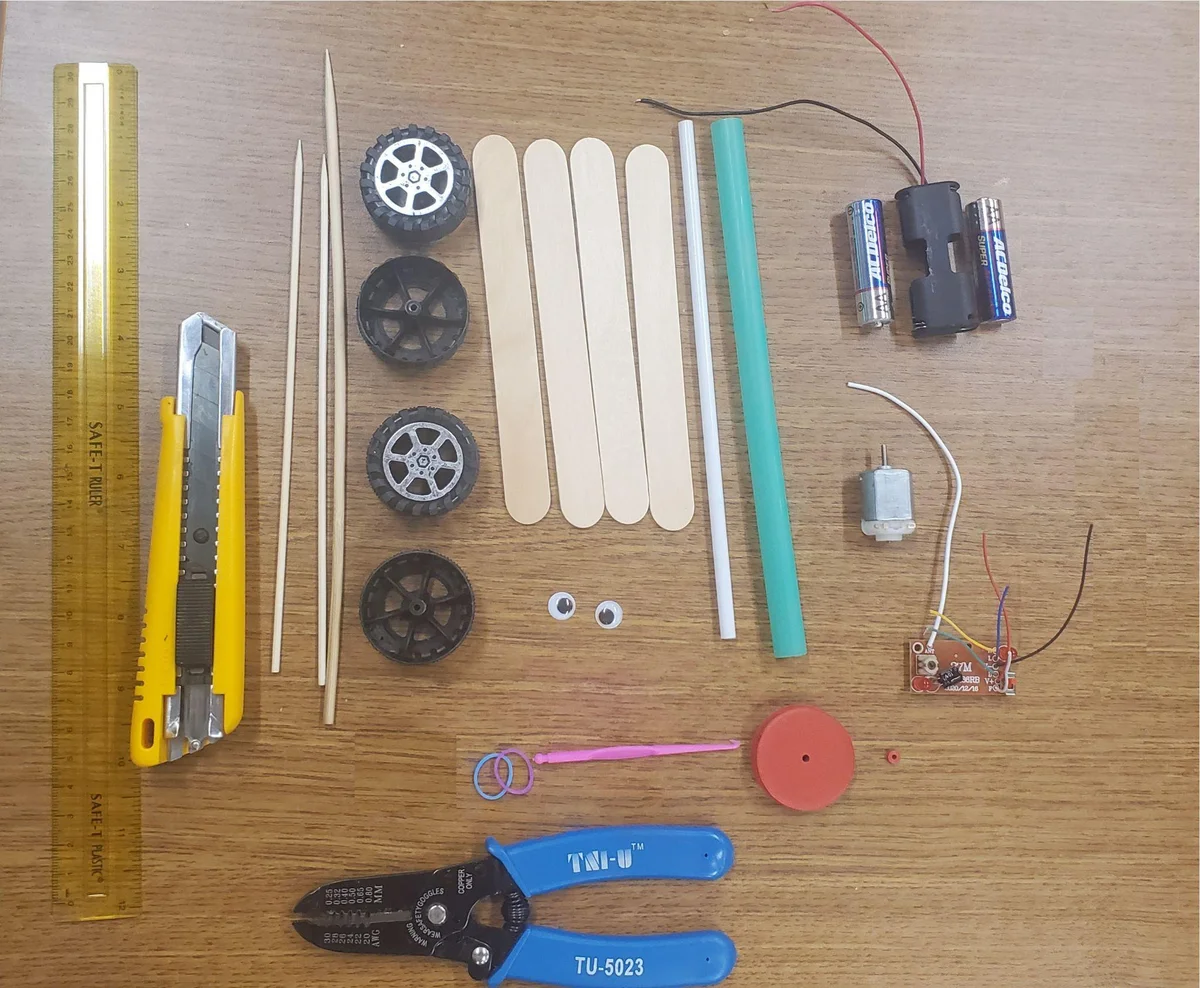
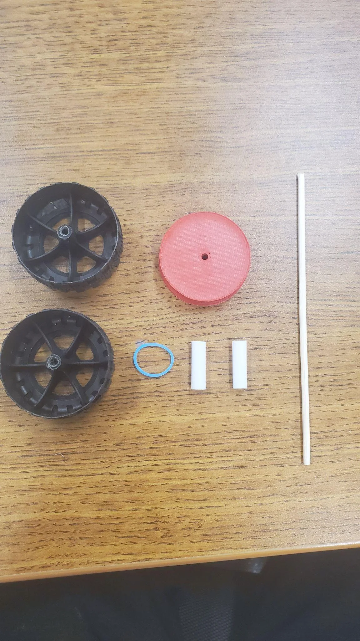
Materials Overview
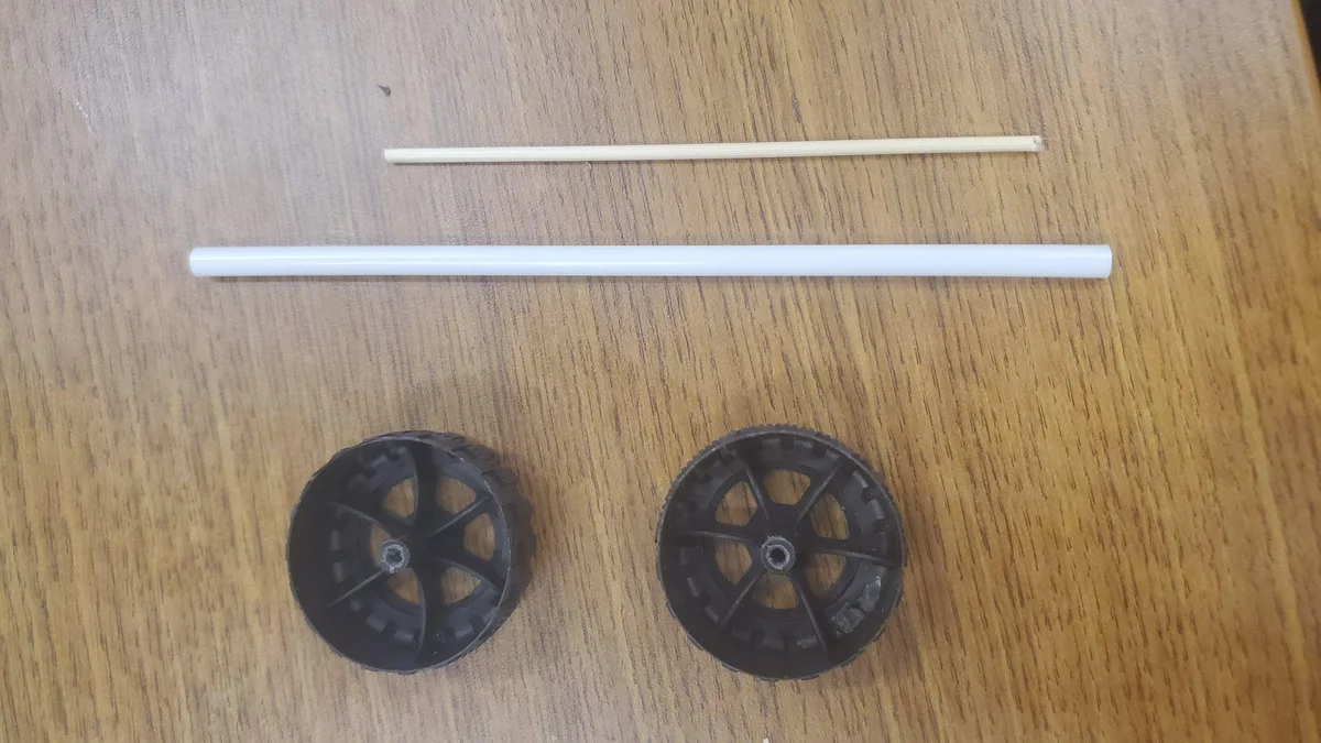
Ensure you have the following components ready for the car assembly:
- 4 Jumbo Popsicle Sticks
- 8” Plastic Straw
- 3V DC Motor
- 2 AA Batteries & Holder
- 2 Thin Skewers (6”)
- 4 Wheels (42mm)
- Loom Band Elastics
- RF Receiver
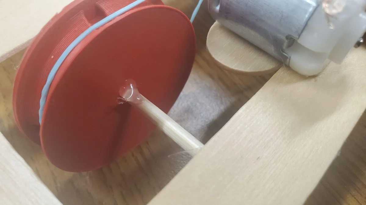
- 3D Printed Wheel Gears
- Bubble Tea Straw (1)
- Googly Eyes (2)
(The thick skewer shown in the photo is used for the controller, not the car.)
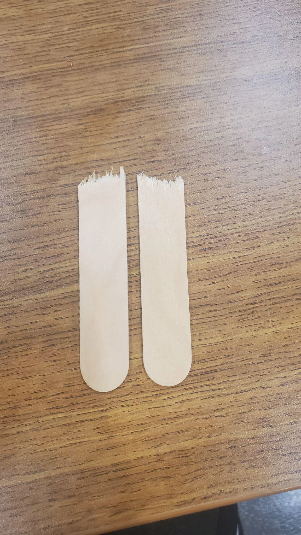
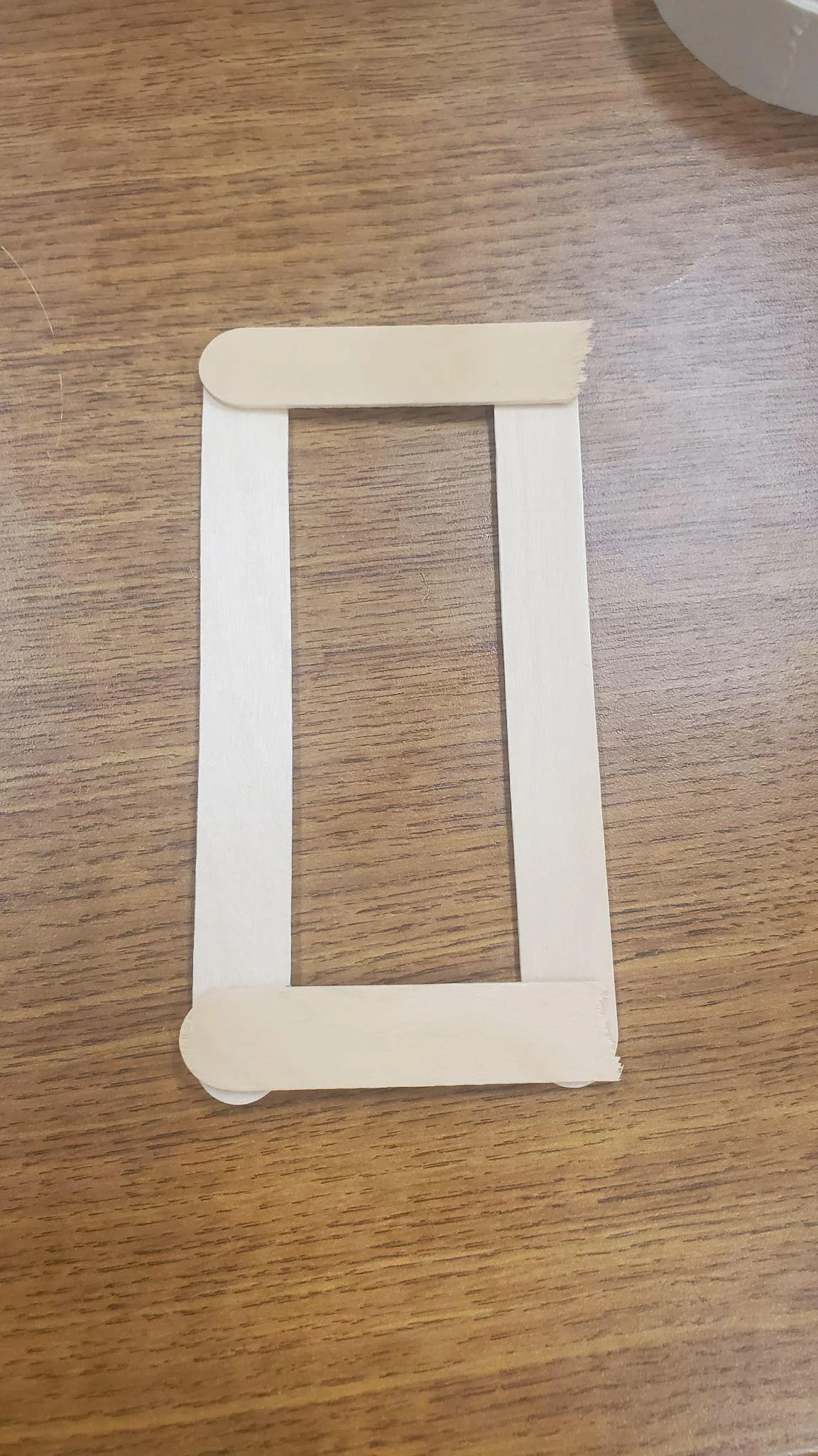
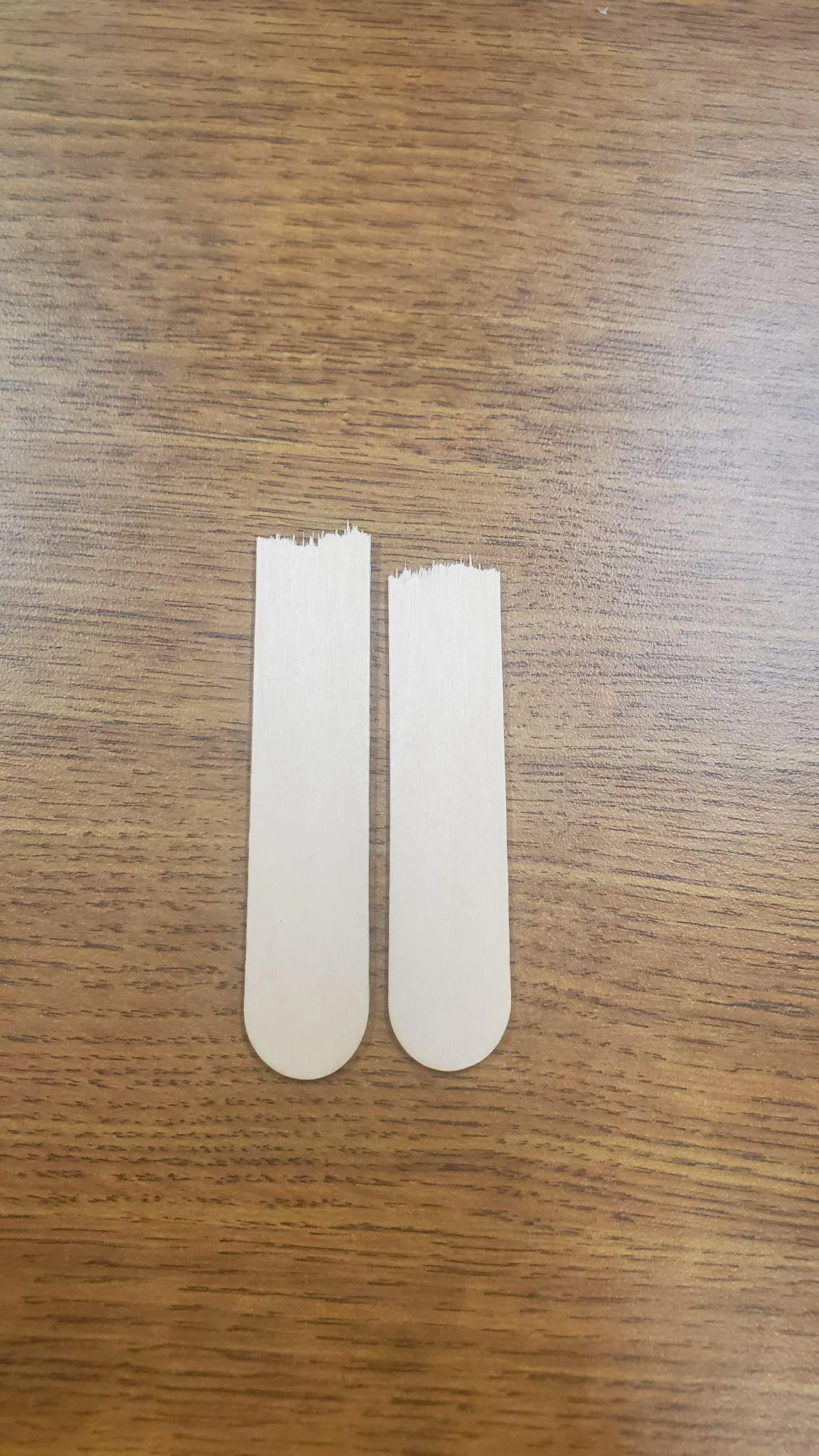
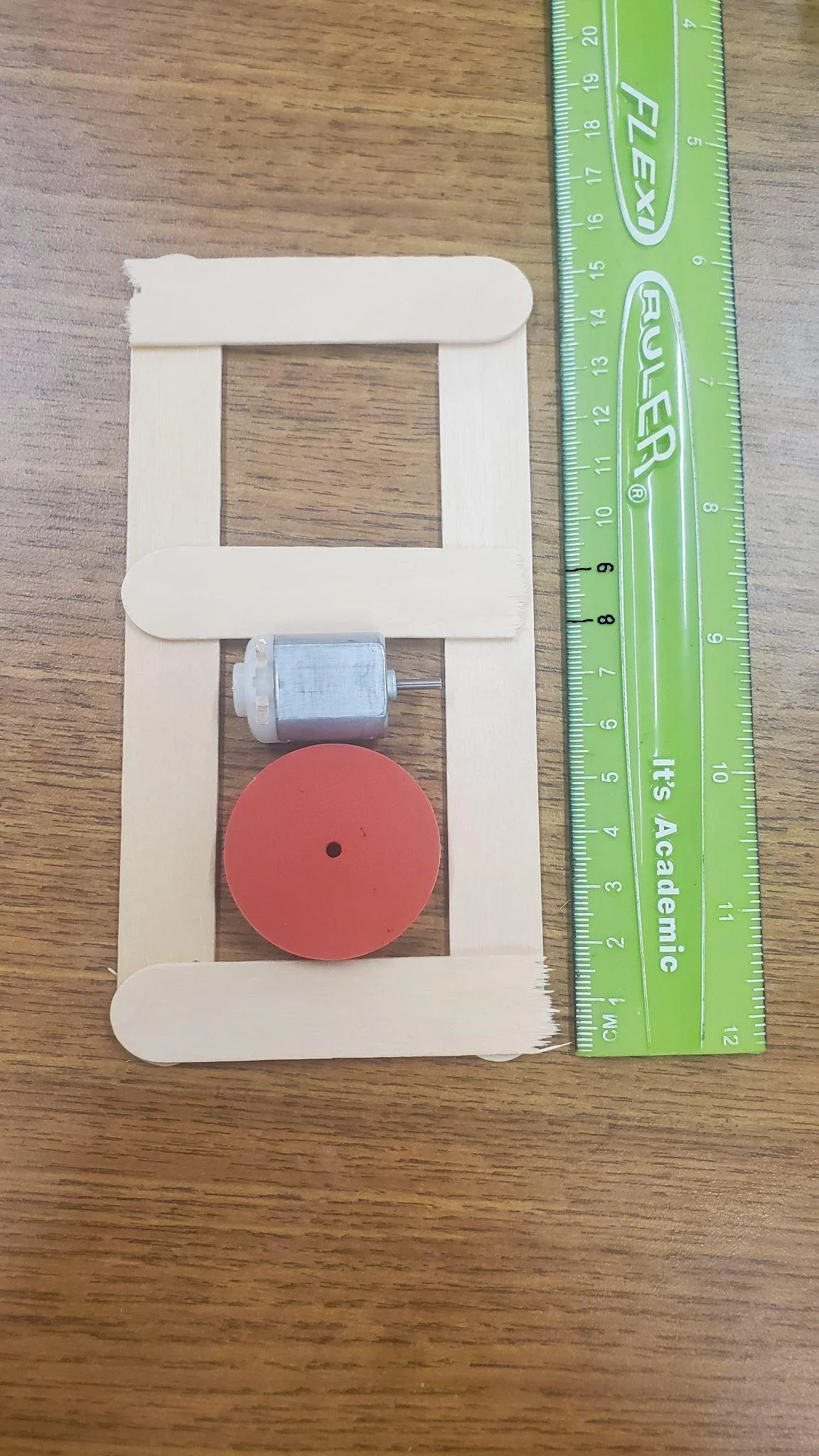
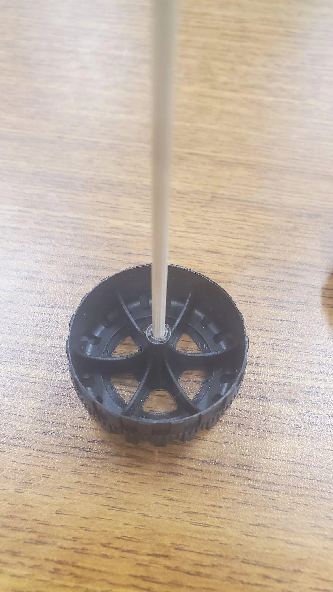
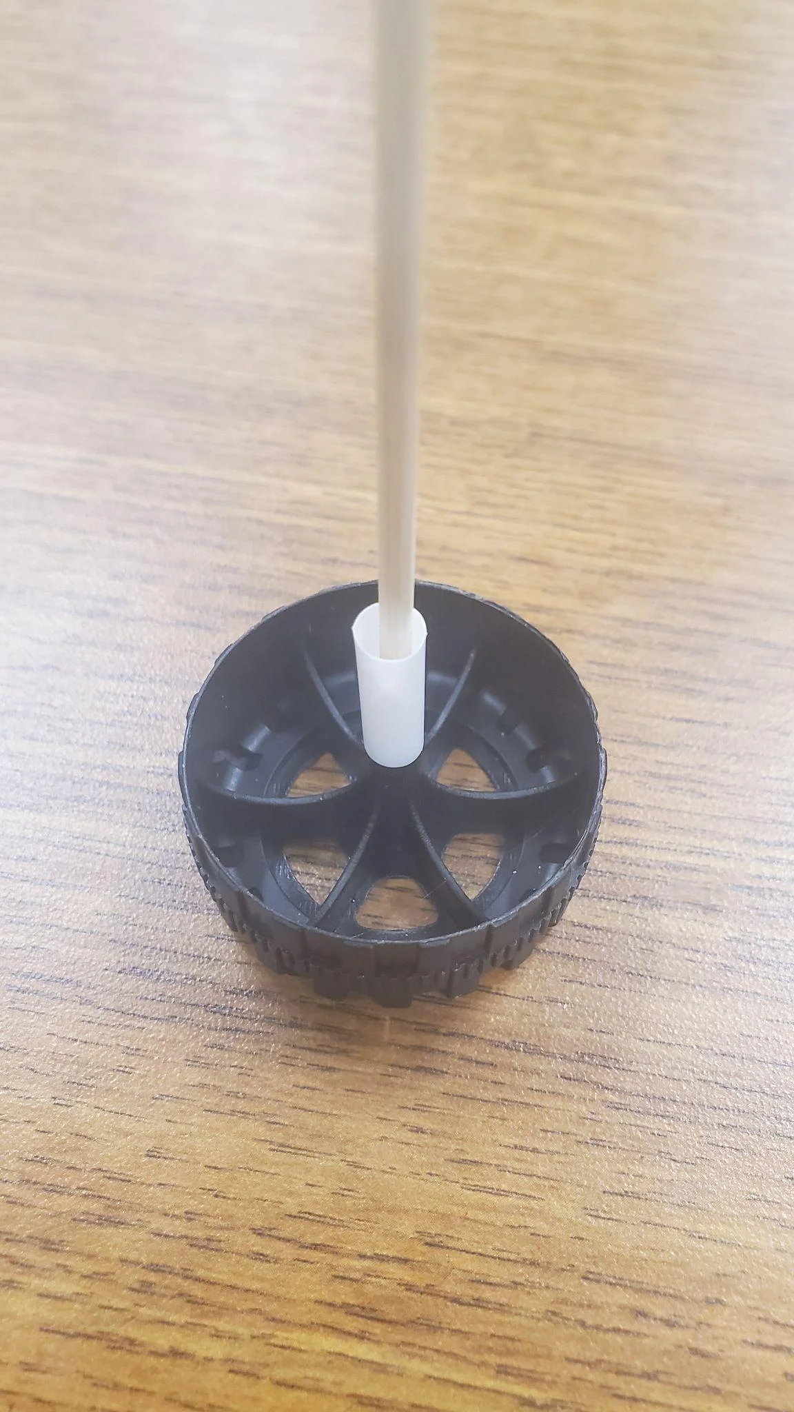
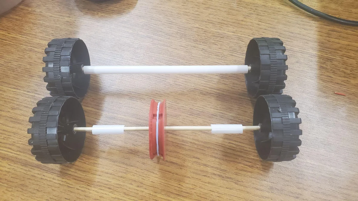
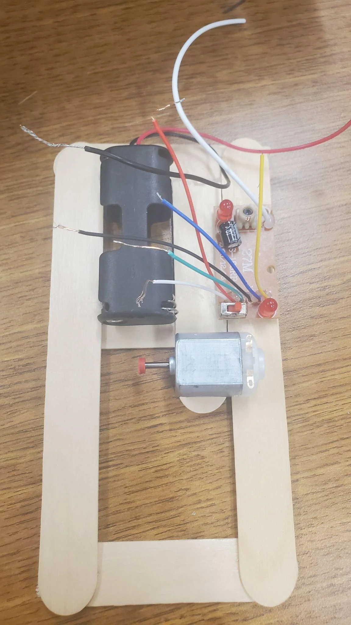
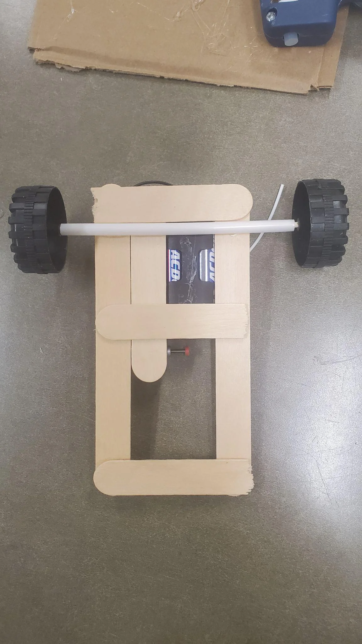
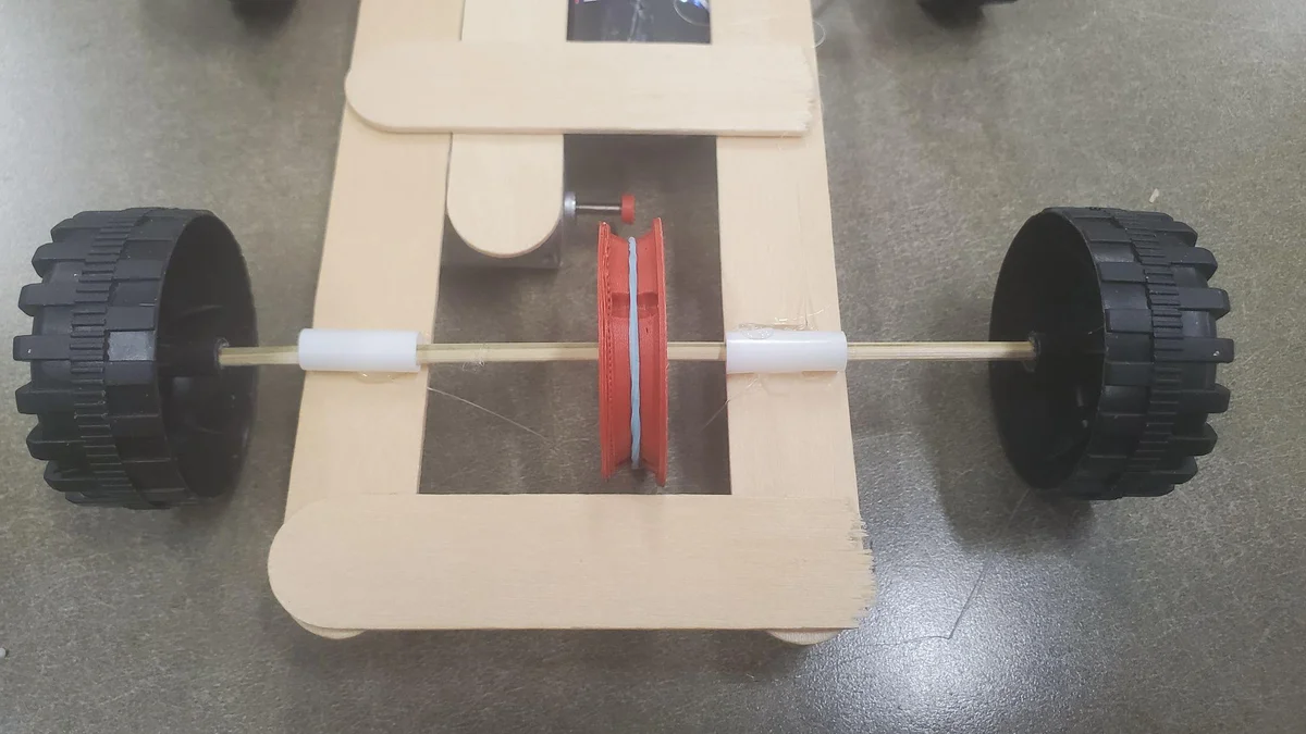
Building the Chassis & Axles
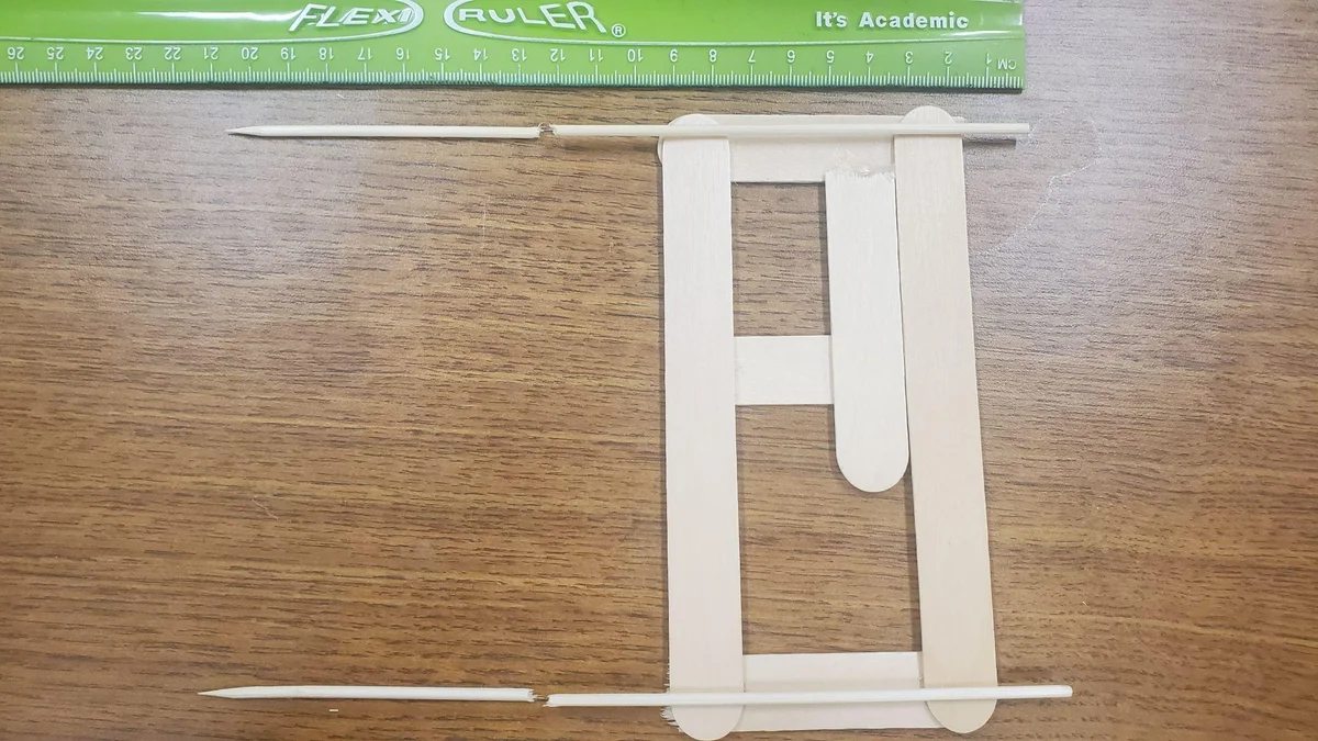
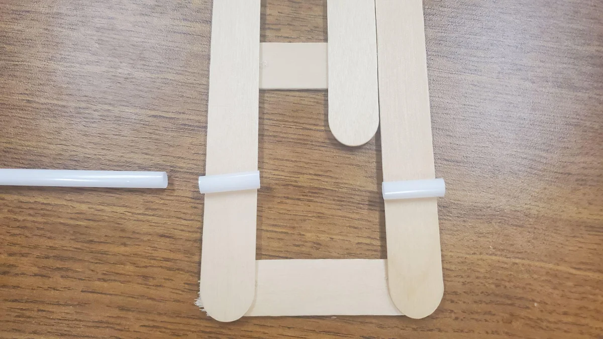
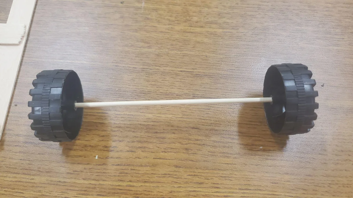
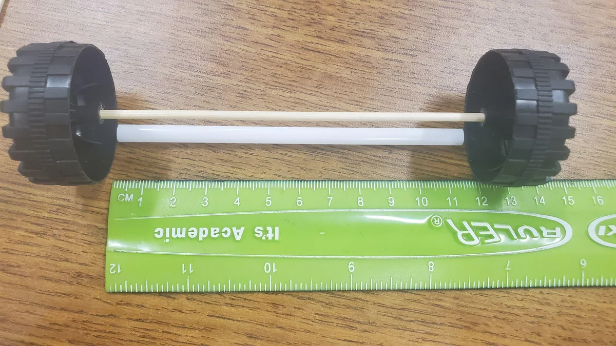
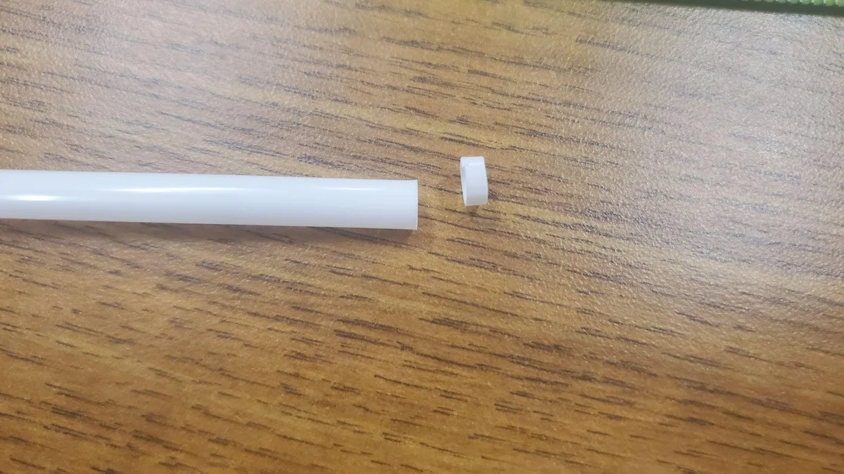
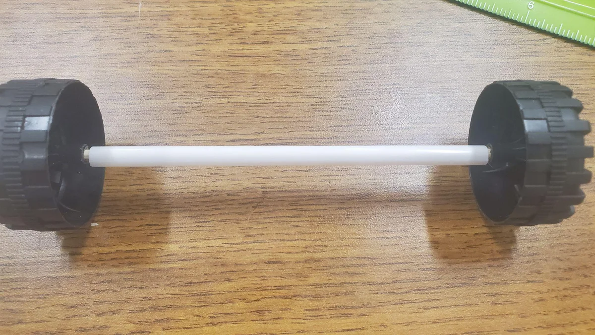
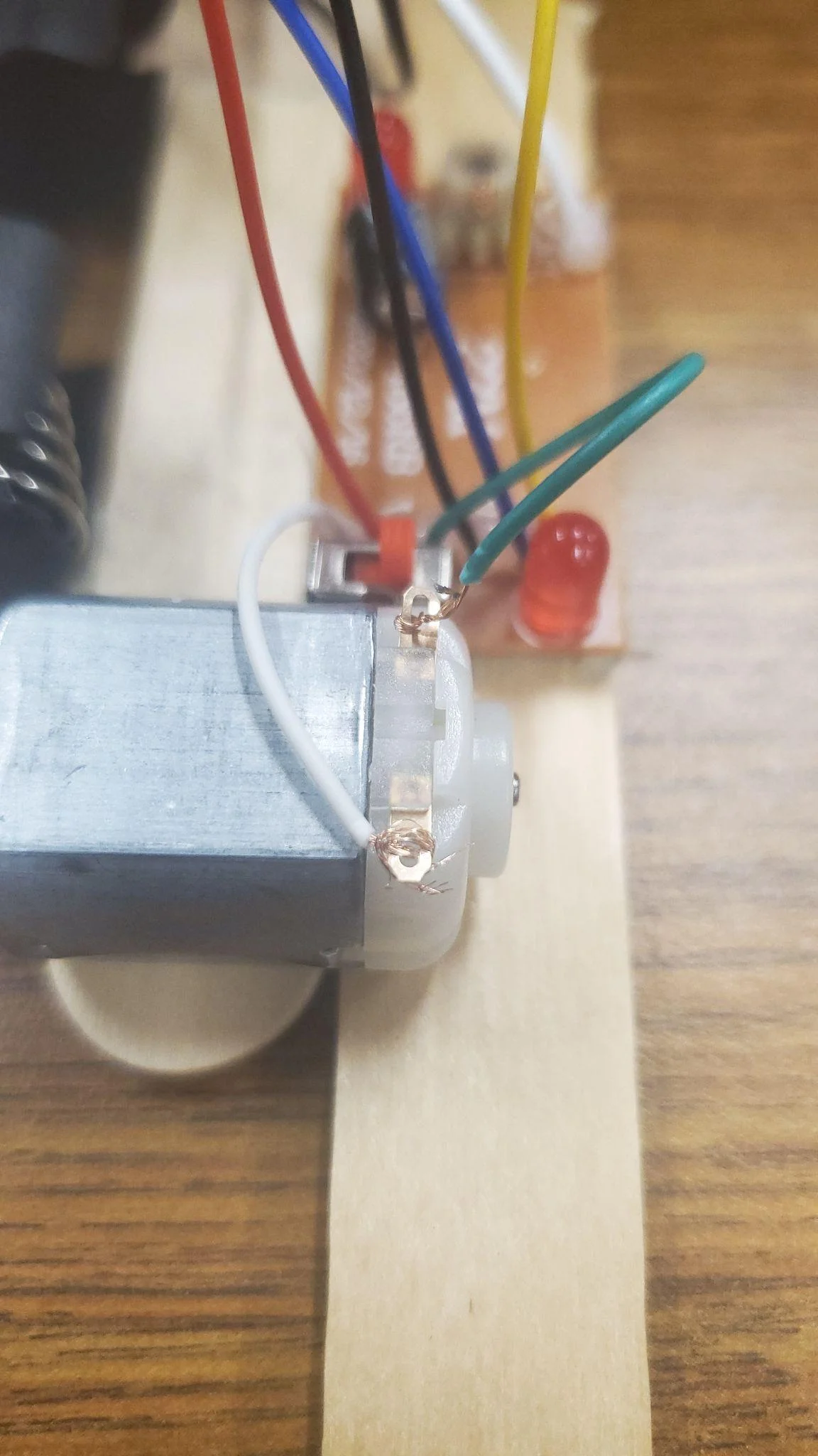
Front Wheel Assembly
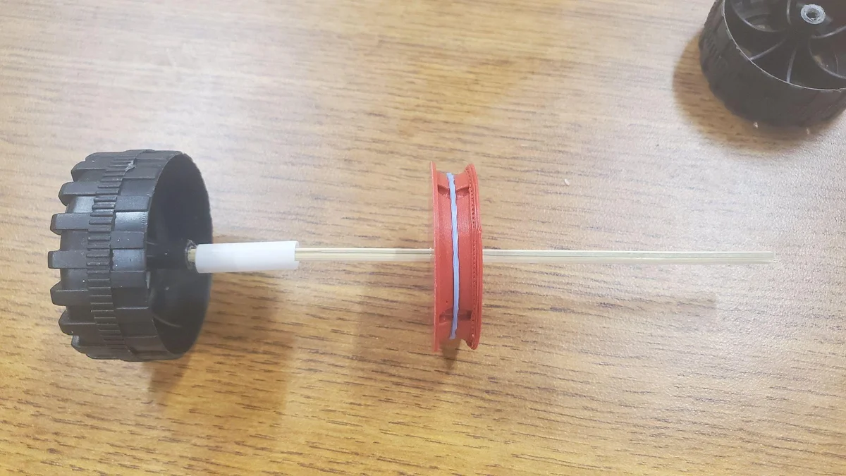
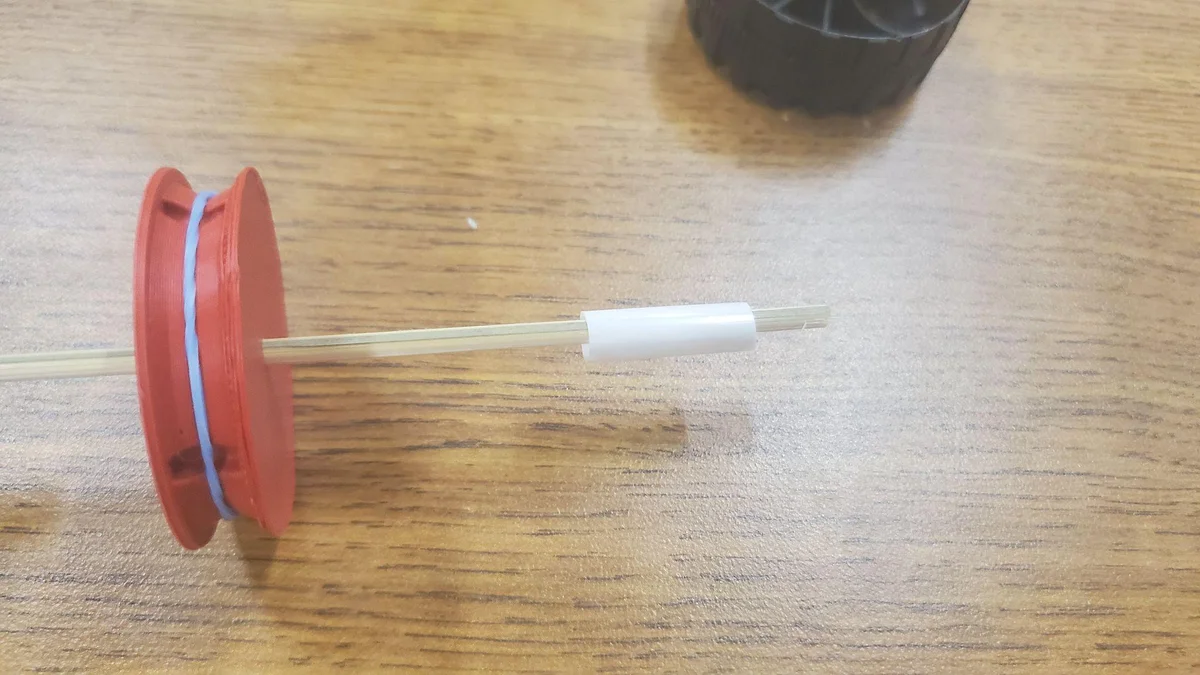
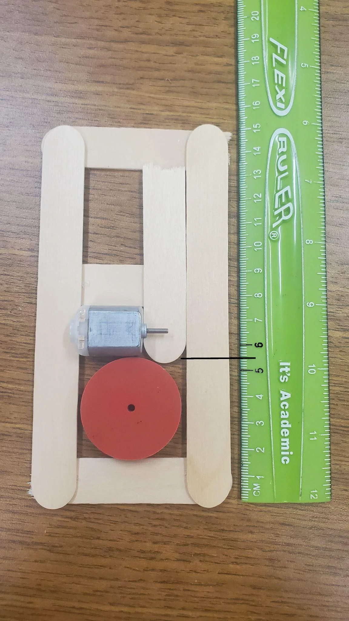
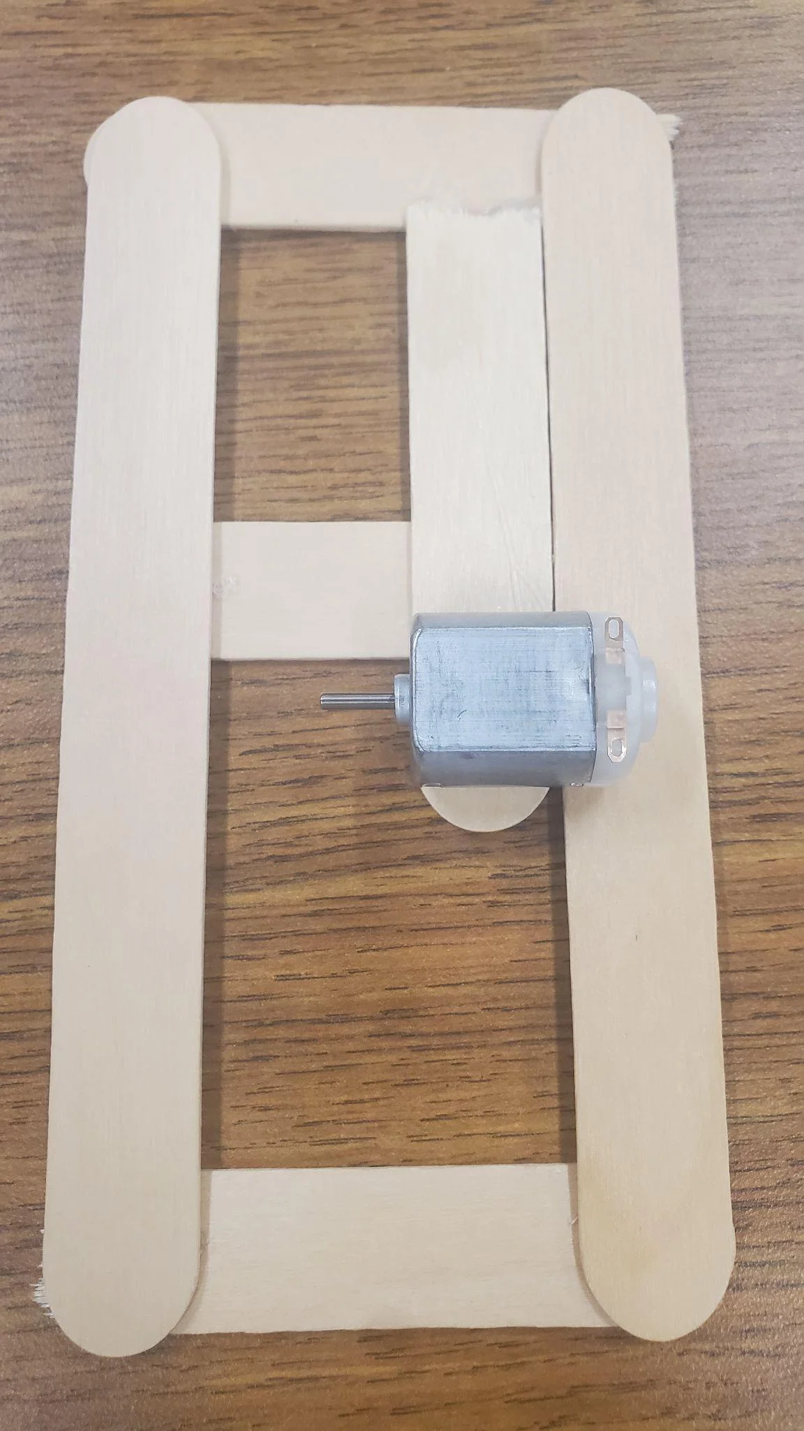
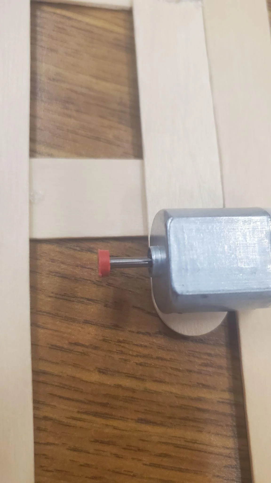
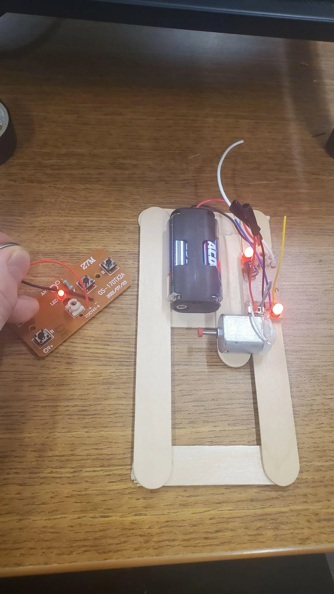
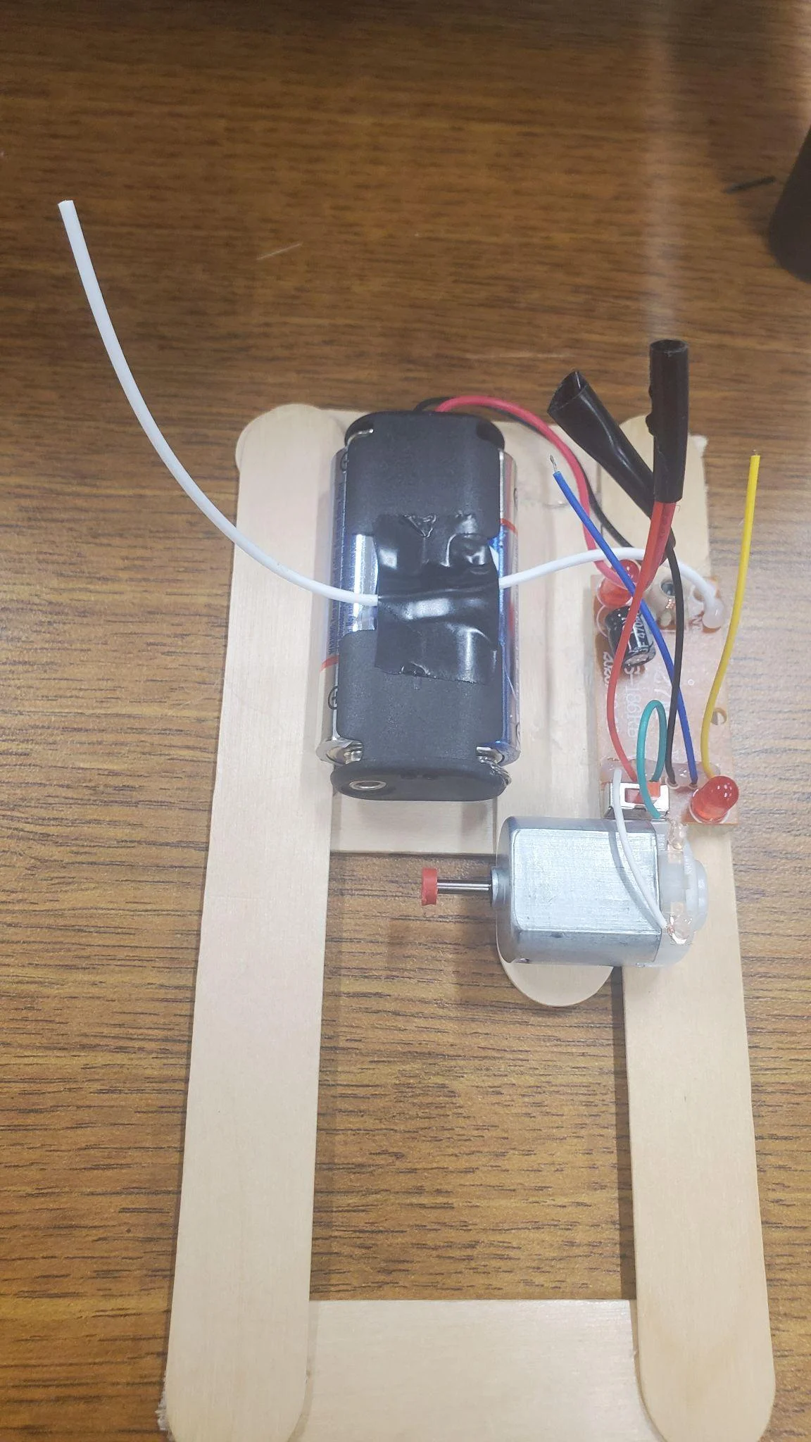
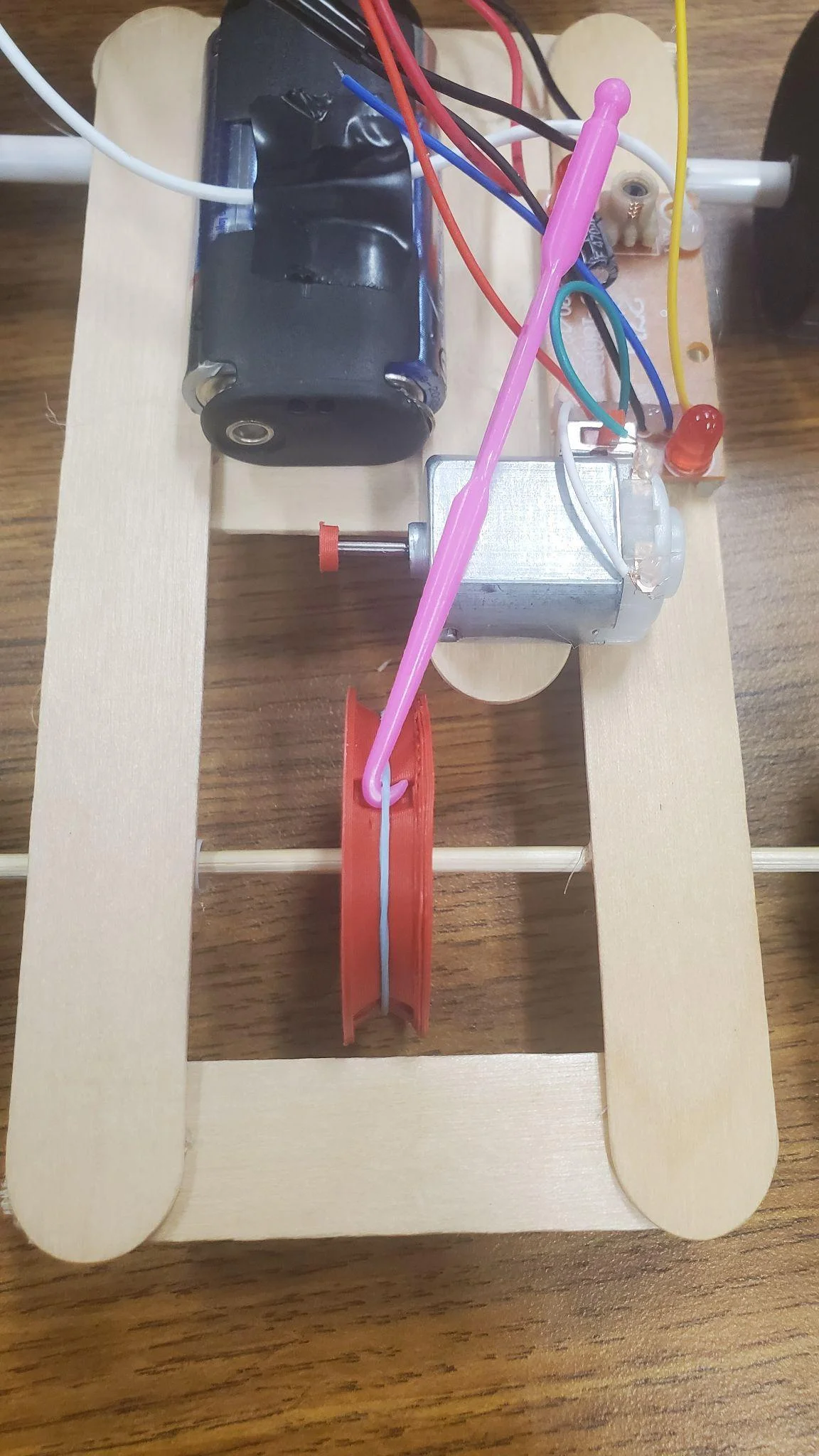
Mounting Components
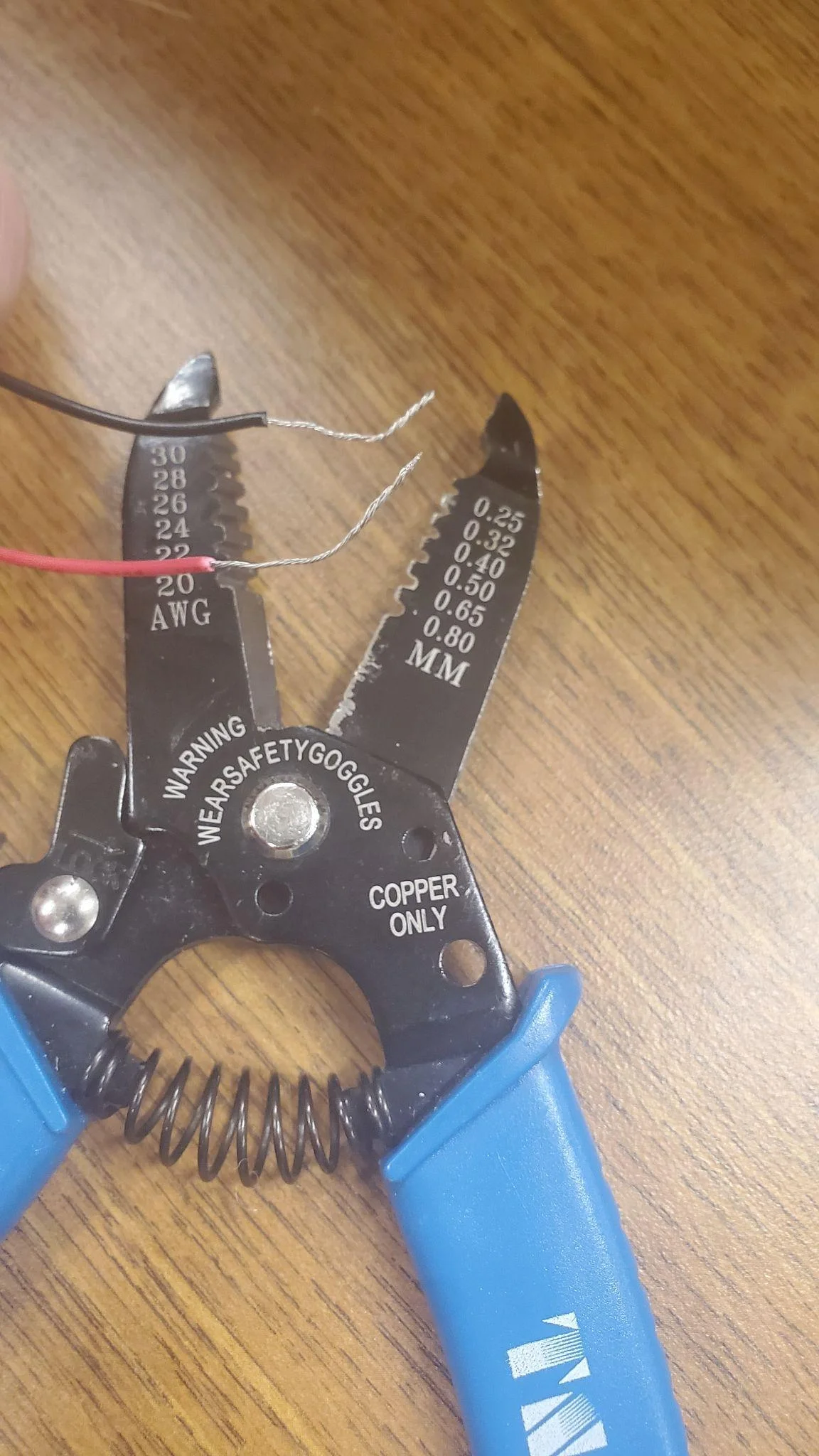
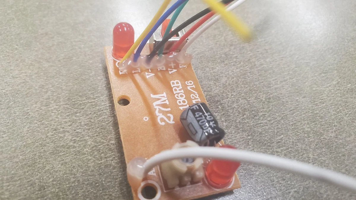
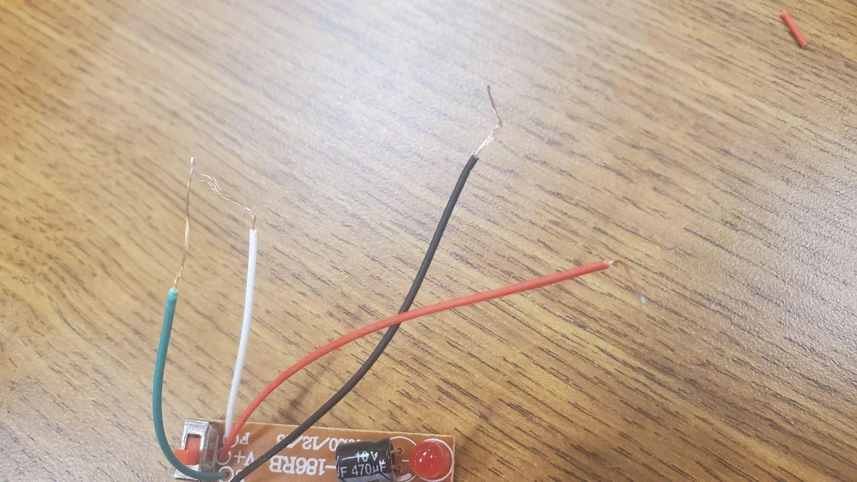
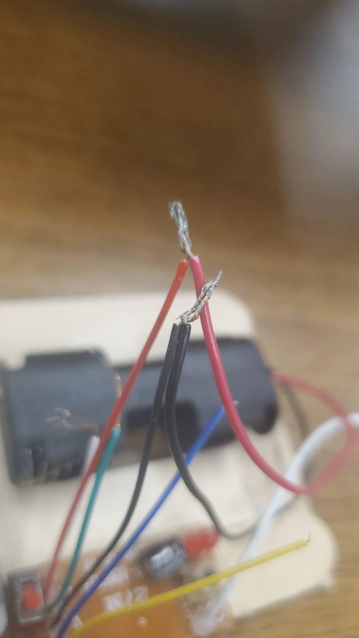
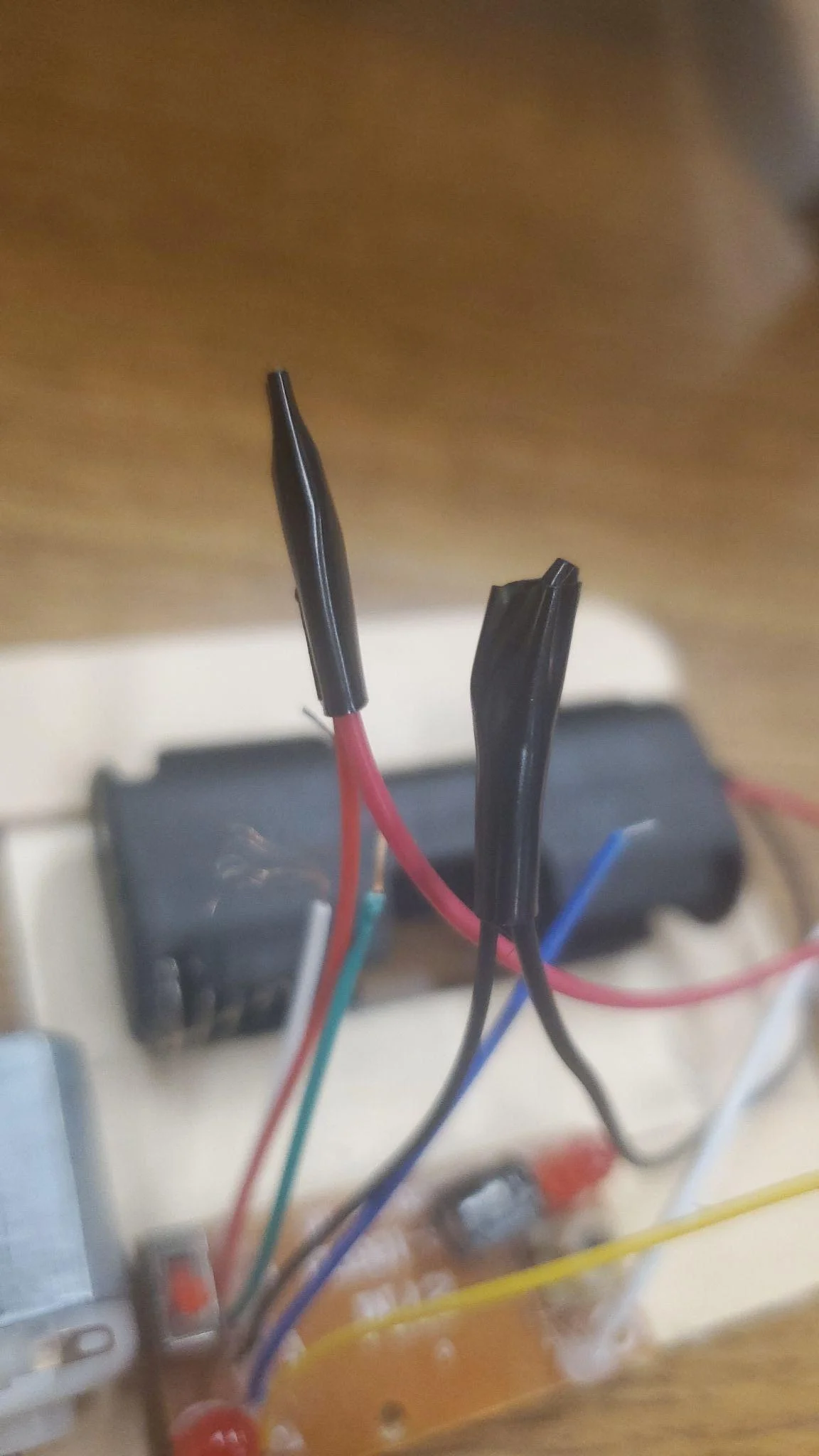
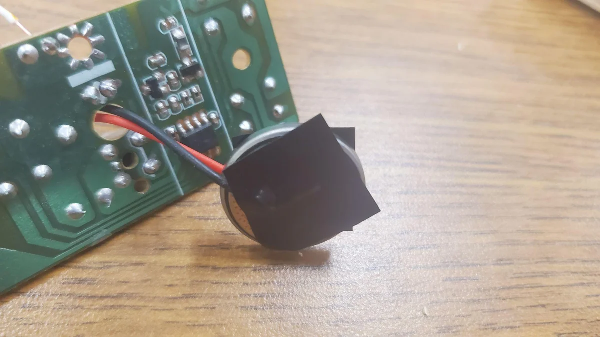
Wiring & Electrical
Final Car Assembly
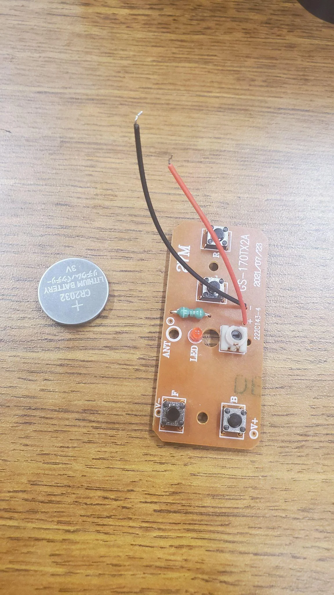
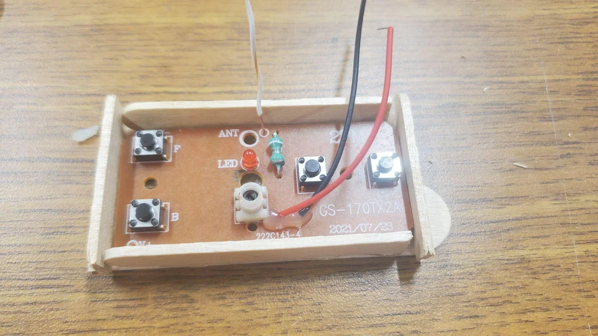
Part 2: The Controller
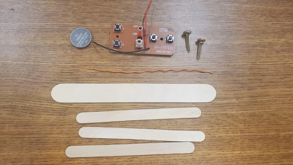
Materials Overview
Gather the following components for the controller assembly:
- RF Transmitter Circuit
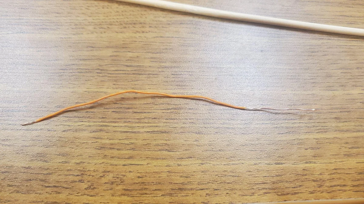
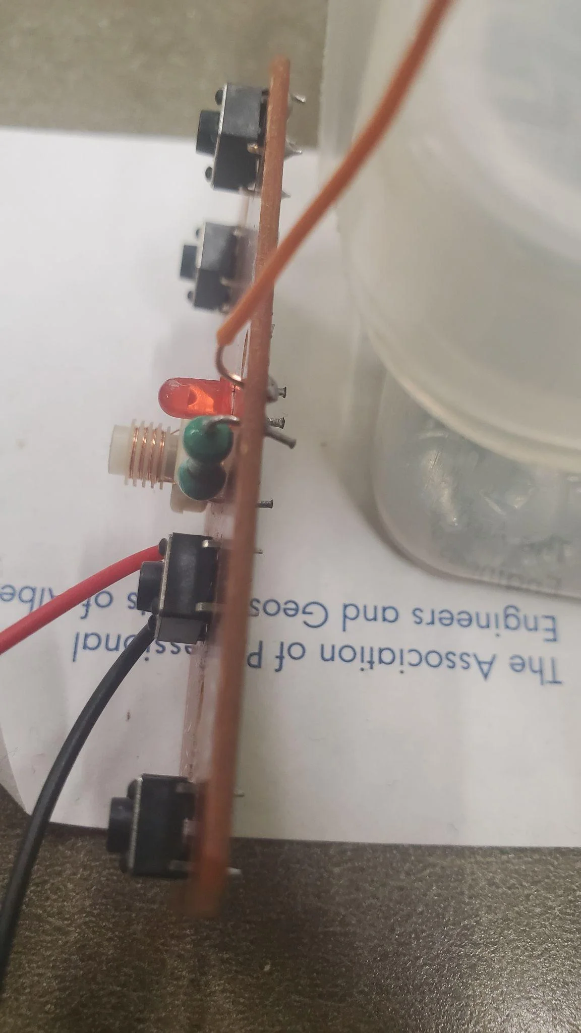
- Stiff Copper Wire (12cm)
- CR2032 Coin Battery
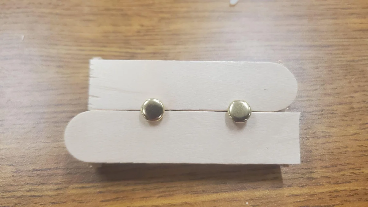
- 2 Brass Fasteners
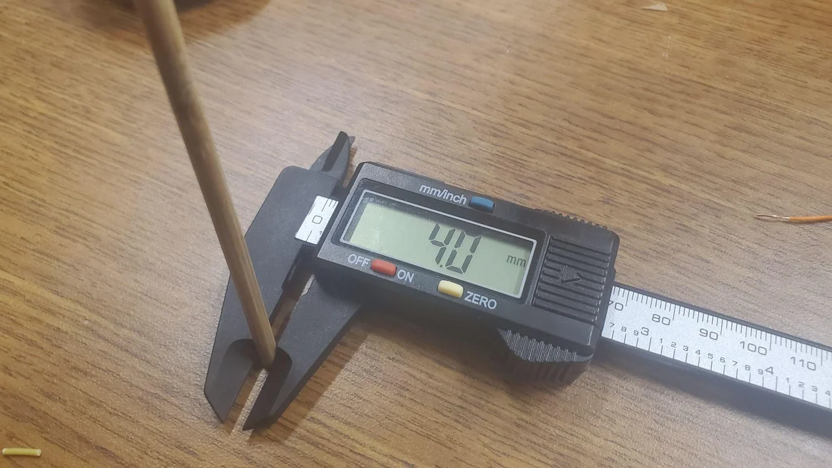
- Tools: Wire Strippers, Skewer (4mm), Hot Glue, Ruler, Tape
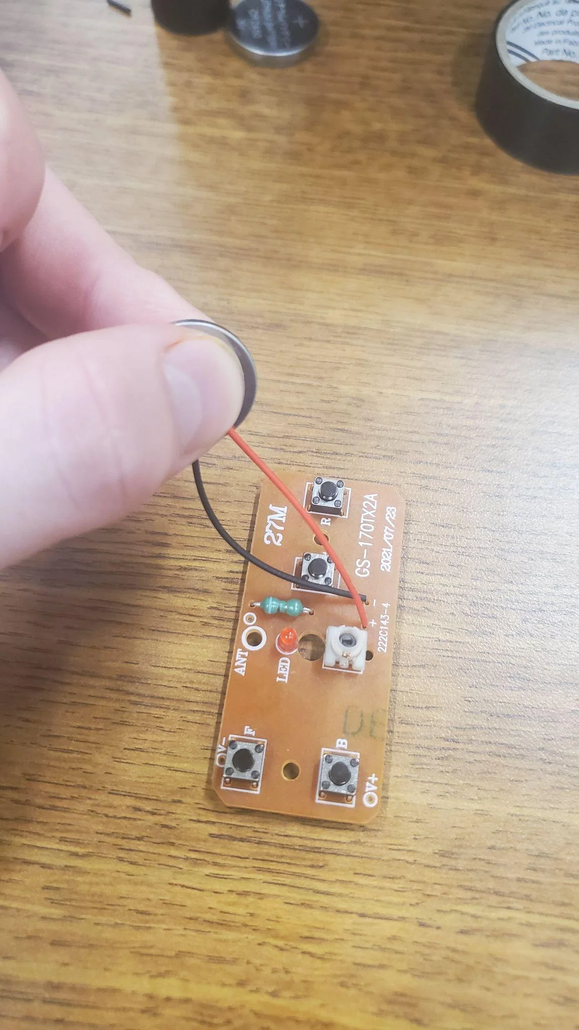
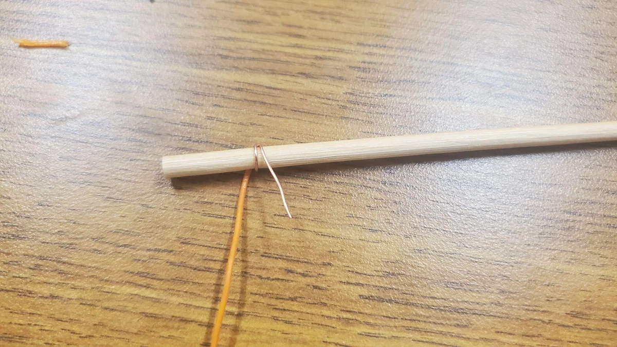
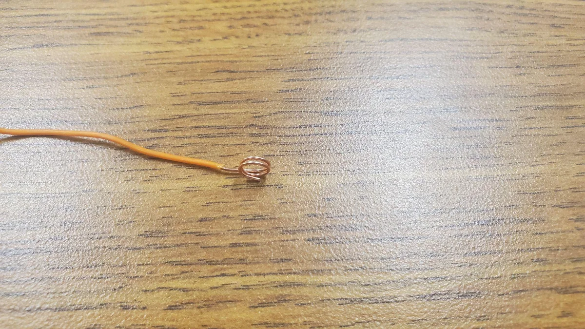
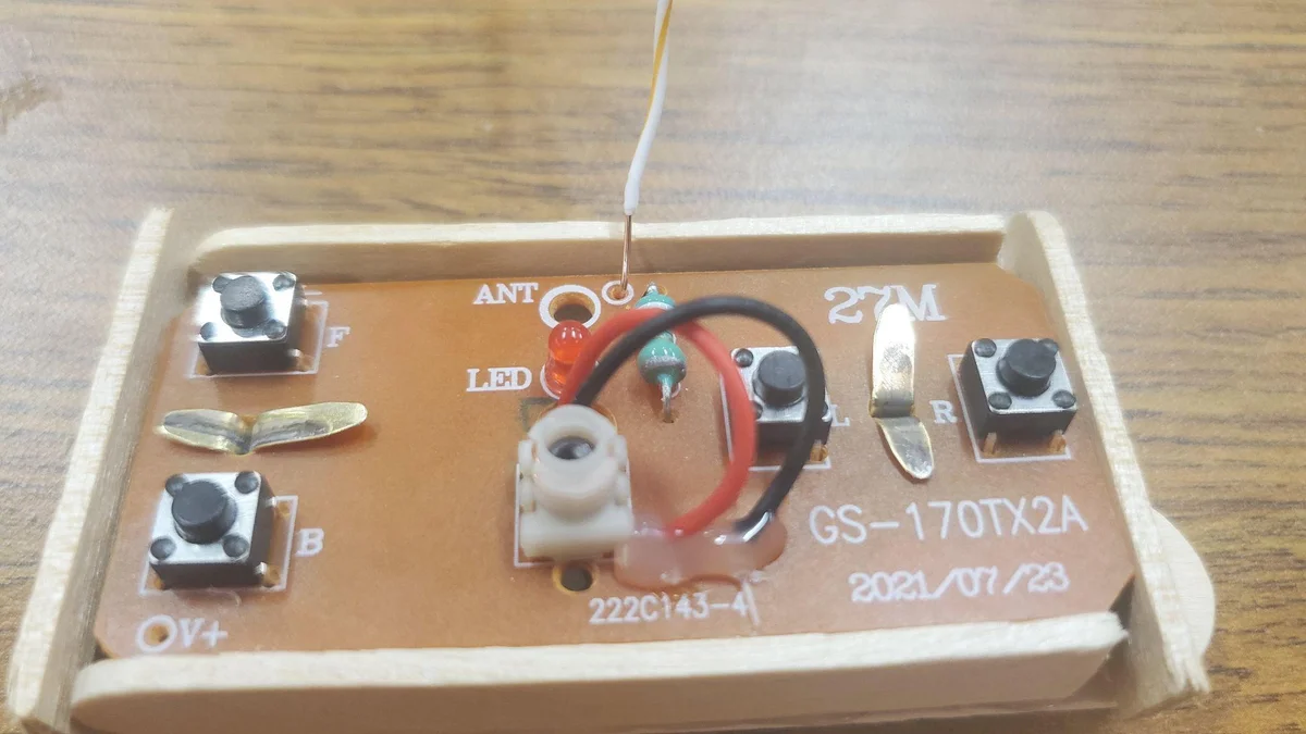
Antenna & Body Construction
Your Mission
You've built a functional, AA battery powered vehicle that can zip forward and backward. But a truly great engineer never stops at just "functional." Currently, this car is limited to a single axis of motion.
The Challenge: Design and implement a steering system.
- How could you pivot the front axle while maintaining structural integrity?
- Can you utilize a second motor or a servo to control the direction?
- How would you modify the RF controller to handle left and right commands?
Take the foundation you've built here and make it steerable. The best designs often come from the simplest materials!